ISO1050: output abnormal: evident error ratio

Part Number: ISO1050

Tool/software:

Hi there,

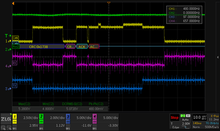
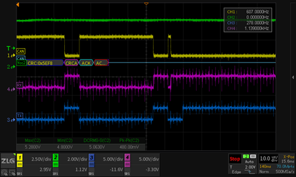
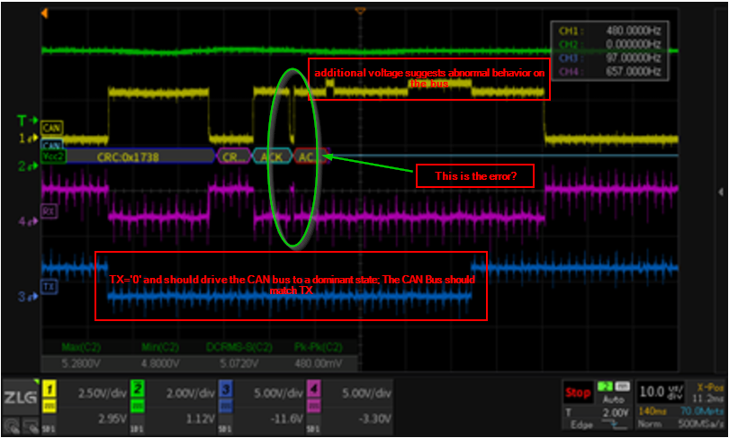
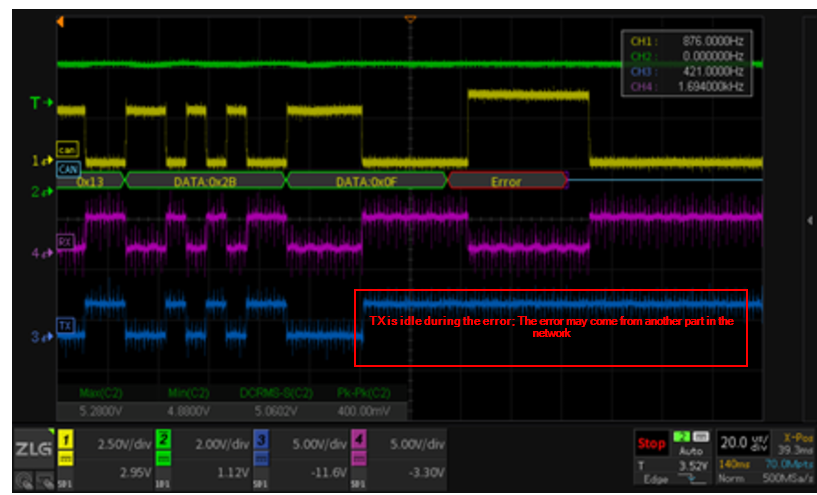
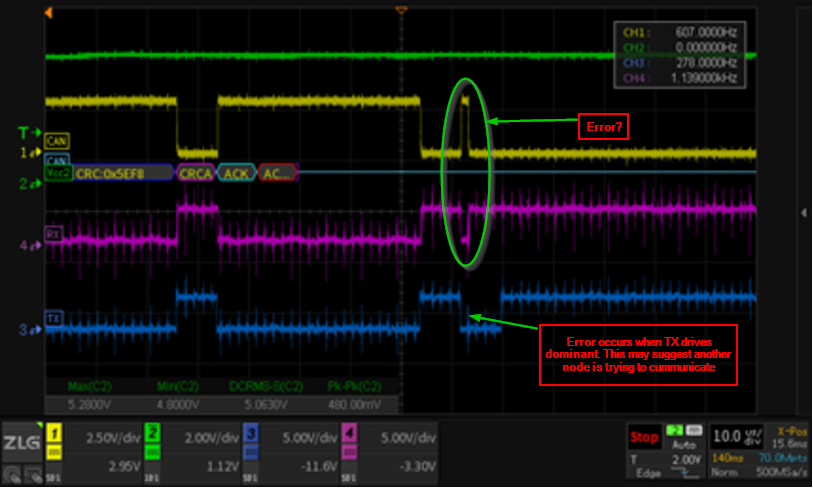
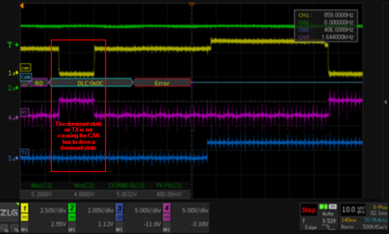
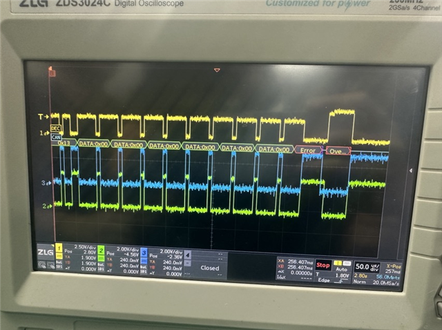
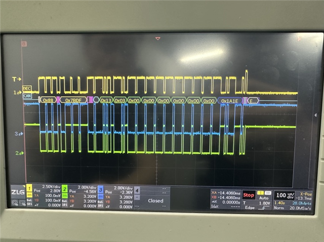
This is Racheal from AA3 Shenzhen team. My customer use ISO1050 in their products and find that there is a high error ratio. They scoped the signals of the device, results shown below.   
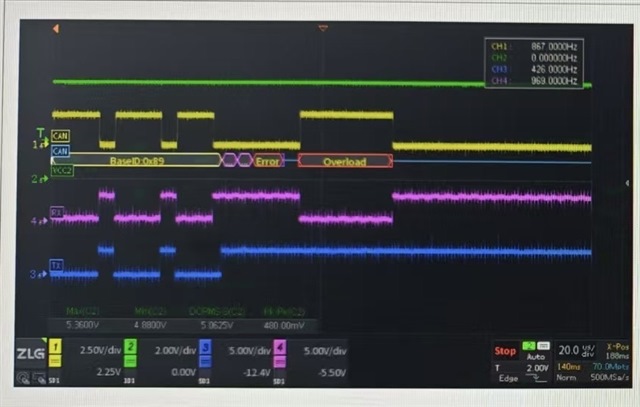
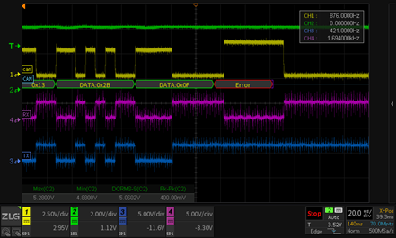
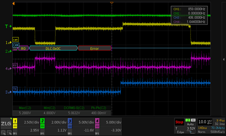
The yellow is CAN differential signal. The green is VCC2. The purple is RX. The blue is TX.

The schematics is shown below.

Seems the VCC2 is stable and did not exceed the recommended range. Could you please help with this issue?

Thanks

Racheal Shen

  • Hello Racheal, 

    Thank you for reaching out. Please see my questions/comments below.

    1. One possible cause is that the TXD is triggering the dominant timeout condition. The maximum time TXD can be held low (dominant) is 1.2ms. How long is the TXD driven low?
    2. How is the error being detected? Is it a missed frame? 
    3. The TXD and RTXD signal looks noisy which is unexpected for the isolated MCU side. What is the cause of this noise? 

    Best,
    Andrew

  • Hi Andrew,

    I am FAE Travis also support Racheal's customer. Update some data to you. Yellow is differential CAN; Magenta is RX; Blue is TX; Green is VCC.


    For your questions:

    1. The TXD low time will not exceed 50us, and the dominant timeout condition is not triggered.

    2. The error occurs randomly with random duration.

    3. The noise in TXD and RXD is introduced by oscilloscope probe.

    It can be seen that the CAN differential voltage will also change randomly (see the last two figure).  The project is 40kW charging station module. PCBA is glue filled. The customer replaced ISO1050 by NSI1050 (Novosense, Pin2Pin), the failure rate has been significantly reduced. Do you have any new idea about this failure?

    Thanks and Best Regards,

    Travis

  • Hello Travis, 
    I currently suspect some bus contention in your application since the waveforms do not look as expected. Based on the scope captures it looks like signal is having trouble reaching the ISO1050 TXD pin or the ISO1050 is currently in a DTO condition which is preventing the ISO1050 from driving the bus 'dominant' when TXD goes 'low'.  

    • Can you please show me where on the schematic each waveform is measured and a full schematic?
    • The signals should be measured directly at the device pins. Can you also show where on the original post's schematic Rx and Tx are measured? 
    • Is Q16 installed during the test? 

    Currently it looks like there is some bus contention and another node may be driving the bus at the same time. 

    Best,
    Andrew

  • Hi Andrew,

    The Q16 is not installed on the test, and the TX, RX waveform are directly measured at the ISO1050 device pins (As marked at schematic). The customer schematic is confidential, but they say there is only one device on the bus, so no bus contention. I have also checked the supply voltage, the 5V VS is stable and the voltage spikes and ripple is less than 200mV.

  • Hi Travis,

    Can you please share the values of R166, R184 and R185?
    Can you please also ask customer to remove them and test again?


    Regards,
    Koteshwar Rao

  • Hi Koteshwar,

    R166  = float, R184 = 10k, R185 = 620Ohm, R112 = 0Ohm, R104 = 3.3k, R143 = 10k, R1 = 5.1Ohm, C1 = 33pF and R167 = 0Ohm.

    The customer removed R166, R184 and R185, the error frame still occurs.

    The ISO1050 is used in a 40kw DC-DC charging pile module. The error frame ratio goes high as the charging module power increase. When output is disable, it has no frame error report. The left figure is the error CAN signal under 40kw full load output. And the right figure is the good CAN signal under 5kw light load output. (Yellow is CAN, Blue is TX, Green is RX):

  • Hi Travis,

    Thank you for reaching out. Most TI employees are currently away from work due to Christmas and New Year holidays. Please allow us to come back to you in the week of 6 January 2025, thanks.

    Regards,
    Aaditya V.

  • Hello Tavis, 

    Unfortunately, the information provide here so far doesn’t point to any clear root cause. Does the unit recover after the error? Does it recover after some time, a power cycle or is it damaged after the error? 

    I suspect that the error in frame is the result of an external factor that is not showing up in the above scope shots.