A related question is a question created from another question. When the related question is created, it will be automatically linked to the original question.
If you have a related question, please click the "Ask a related question" button in the top right corner. The newly created question will be automatically linked to this question.
The ISO1228 cannot change the output of a source type input. This is because the active state of a source type input is a short to GND. The MCU will need to invert the source mode logic internally the other truth table is needed.
Please disregard my initial post. After a discussion with my team, the truth table shown in your original drawing is correct. When the sensor is CLOSED the corresponding OUTx will be HIGH. This is because both sink and source mode will output a high when 24V is seen across the INx and LEDx pin.
There is no way for ISO1228 to differentiate between the SINK and SOURCE modes from the MCU side. An external isolation circuit would have to be implemented in order to differentiate between the two modes. The sink source EVM would be the best layout to identify switch between both configurations (https://www.ti.com/tool/ISO1228EVM).
Why does the customer need to identify which mode the input is being used in? The OUTx pins will match the desired truth table shown in the initial post.
To identify whether the inputs are in sink or source mode consider the following: ISOM8110 would be characteristically similar to 150060VS75000 (the green LEDs) so it is possible to use ISOM8110 to indicate when a sink or source mode input is active. This can be done either by replacing D15 and D14 in the schematic or one of the green LEDs (depopulated on the ISOM1228EVM) with an ISOM8110 footprint in your design.
The two pictures below are in source mode; the black switch circle on the left represents an open circuit, yet the multimeter measures the OUTPUT as High.The black switch with a single line on the left represents a short circuit, yet the multimeter measures the OUTPUT as Low.
We followed the datasheet’s recommended wiring for SOURCE mode and used the ISO1228DFBEVM for testing.
This behavior is likely due to the ISO1228DFBEVM. This EVM is the SINK mode EVM. By default, there LEDs on that EVM only support the SINK direction. Each LED needs to be turned around to be operating in SOURCE mode. The logic may be reversed because of some missed connection.
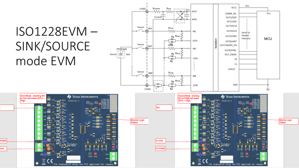
The other ISO1228 EVM - ISO1228EVM - will support SINK and SOURCE mode configurations by providing 2 diodes (one for each direction) on the LEDx pins.
Please include a schematic/diagram showing how you are connecting the switch, power supply and EVM.
I double checked with my team to confirm that this is the correct 'truth table'.
The switch in the schematic looks like is has two poles (DPST). This means that in the 'O' position pins 4 and 5 will short and in the 'I' position pin 5 and 6 may short. Is it possible that the switch contacts are flipped?
OUTx should read a HIGH when shorted to COM (in source mode). Therefore, you can test this with the switch disconnected and shorting the wires where the switch was connected.
I removed the switch and directly shorted the original switch connection points, but the test result still shows LOW; after removing the shorting wire, the output shows HIGH.
I have tested this my self our lab just as a sanity check. OUTx remains 0V on the VCC2 side when the input terminal is open.
In SINK mode (V1 = FGND and V2 = 24V), a short from IN1 to 24V delivers a HIGH at OUTx.
In SOURCE mode (V1 = 24V and V2 = FGND), a short from IN1 to 0V (or FGND) delivers a HIGH at OUTx.
In both cases OUTx is a HIGH when INx is shorted with a wire to the intended state. The ISO1228EVM - which is sink/source mode capable - was used to test.
I have another question. Currently, we are using the ISO1228EVM to plan the circuit. We would like to define the external connection pin define for the power side V1 and V2 as fixed 24V and 0V for the customer, so that the customer does not need to reverse the input power when using SOURCE mode. Do you have any recommended circuit for this approach?
Or, do you know if there are commonly used labeling terms on machine enclosures to indicate that this terminal should be connected to positive or negative depending on the situation?
As you have noticed, the above EVM uses a bridge rectifier to ensure the voltage on AVCC is always 24V and AVSS is always 0V. The EVM connects all LEDx pins through diodes to V1. This configuration makes testing with the ISO1228 easier since a switch could be wired from INx to V1 for normal operation in both SINK or SOURCE mode, and only the V1 and V2 connections would be flipped to when changing modes.
The bridge rectifier also prevents the possibility of reverse wiring and ISO1228 will not be damaged if V1 and V2 are flipped. It would just be in the other mode. Terminology such as FGND, COM1 and COM2 are typical names for these applications.
Thank you for your reply. I have another question to ask.
According to the "Device Functional Modes" in the datasheet, when (INx) = High, (OUT_EN) = High, (OUTx) = High. Is this condition also the same in source mode?
Because when measuring in source mode with a voltmeter, the result (as shown in the figure) does not match what is written in the datasheet.
Could it be that I measured at the wrong test point? Or is 3.3V already considered as High?