This thread has been locked.

If you have a related question, please click the "Ask a related question" button in the top right corner. The newly created question will be automatically linked to this question.

ISOUSB111: Circuit Review

Part Number: ISOUSB111

Tool/software:

Hello Team,

We were getting USB Comminucation data corrupt in Our Industrial application with Customized Board.

We have tested through ISOUSB111 EVM board Successfully and Now we are planning to make USB Isolated converter using ISOUSB111.

Can you help us to review the schematic and have your valuable suggestion to proceed.  

Our reference is EVM only.

Difference is :

1. For ESD, EVM uses separate ESD diode , but we used , Texas dual channel TPD2E2U06DRLR part , Not sure why it is ommited from TEXAS EVM... 

2. USB Connector shield connected to PCB GND , Not sure if It is Good Practice or Not ? we uses RES / CAP pair.

3. pin 8 and 9 Connected to ground through Zero ohm Resistor , In Our case , connected directly to GND.

  • Hi Bhupinder,

    Over all it is good but wanted to highlight some observations so that you're not missing any thing:

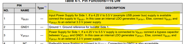
    1. I see that V3P3Vx are not supplied externally which means you have a 5V supply on both the sides. Datasheet mentions the supply connections.
    2. The EVM has 5V powers via VBUS on UD side and 3.3V [powered on DD side.
    For ESD EVM uses separate ESD diode , but we used , Texas dual channel TPD2E2U06DRLR part , Not sure why it is ommited from TEXAS EVM... 

    The ESD Diode on Data lines is totally optional and should be customer's decision based on the end usage environment.

    Regards
    Varun

  • Thank you, Varun

    For Pointing Out Critical points.

    Yes, Both Side 5VDC only. We used 5V-5V Isolated Convertor.

    Any comments on Point 2 for shielding ?

    Can I share Schematic on Email and Take Further communication ?

    Regards,

    Bhupendra

  • Hi Bhupendra,

    Somehow the Points 2 and 3 were not visible in your original post earlier. Also, I don't see the schematic picture anymore, looks like you have edited your post after my response. What's going on here?


    Please find my inputs below on points 2 and 3:

    2. USB Connector shield connected to PCB GND , Not sure if It is Good Practice or Not ? we uses RES / CAP pair

    Yes it can be connected to PCB GND directly. I have personally not seen shielding using RES/CAP pair, Can you please a reference for me to read which discuss about this. Highly appreciate sharing knowledge on this forum!


    3. pin 8 and 9 Connected to ground through Zero ohm Resistor , In Our case , connected directly to GND

    No Issues here, You can connect pin 8/9 directly to PCB GND just like pin 2/15.

    Regards
    Varun

  • Hello Varun,

    My Team Suggested to share it personally on Email Considering IP. Would that be fine ?

    For Point 2 , Generally , Shield already connected to host side , connecting it other end may cause Ground Loop current. Capacitor is used for Bypass AC Noise to GND from Shield.

  • Hi Bhupendra,

    We will reach out to you over email by tomorrow EoD.

    Let's discuss the shielding technique over email as well.

    Regards
    Varun

  • Sure , VARUN
    Thank you.