ISOW1412: DC to DC Converter Startup Issue

Part Number: ISOW1412
Other Parts Discussed in Thread: PROFIBUS,

Tool/software:

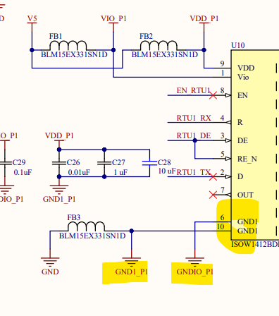
I have an ISOW1412 that is configured like the datasheet articulates for a half duplex interface. I am having a problem with the DC to DC Isolation regulator drawing high current before it starts to regulate, this can go on for several seconds and cause the device to get very hot, it starts out at the Clamp voltage and then eventually down regulates to the proper voltage. This happens in both the 3.3V Output configuration and also the 5V Profibus configuration. If I allow the VDD and VIO which are both configured for 5V to come up with the EN pin pulled to ground the device is initially disabled and draws only 20 mA or so staying cool, if enable is then brought high the high current draw occurs. So the issue occurs both when starting enabled and allowing VDD and VIO to ramp up as my 5V regulator comes up and also in the absence of any power sequencing issues using EN. Once it starts regulating a quick power cycle will regulate in a few milliseconds, if its allowed to sit a while the high current draw occurs again. What would cause this behavior.

  • Hi Roy,

    Thanks for reaching out.

    Please share the schematic connection for us to review. This is important for us to provide any comment on regulation

    Also, you need to mention the current numbers here for us which you think is on the higher side.

    Few comments which you can check quickly in your schematic:

    1. Make sure that VIO is always on when you power VDD - needed for feedback regulation
    2. VISOUT and VISOIN must be connected externally
    3. EN pin should be pulled high to VIO level and not VDD

    Regards
    Varun

  • RS485_ISO_B.pdf

    Here is the requested schematic, the VIO and VDD are common at 5V and I am using Profibus mode. For some additional clarity when the regulator starts correctly it takes 2 milliseconds to begin regulating to 5V, when it does not it can take 20 - 30 seconds before regulating properly, during this time no Fault signal was generated and if I monitor the VISOOUT voltage it quickly goes up to almost the 6V clamp voltage and slowly decays down until it falls below 5.6 volts at which point the regulator starts and it drops below 5V and starts to regulate. I have tried changing the bulk capacitors C23 and C25 from the ceramic dielectric ones used on your evaluation board to Tantalums to increase the ESR so that the initial VISOOUT voltage stays below 5.6 volts without much success. I am considering what may happen if I add a 5.4V Zener on VISOOUT load point to accomplish the same.  

  • The current draw on my 5V supply is 350 mA when it is not regulating properly and drops to 27 mA once regulating.

  • Hi Roy,

    Based on the Schematics, the GNDIO and GND1 pins are not at all connected which is what is making the device go out of regulation.

    Please fix this connection as per datasheet and test again to see the true device behavior.

    Regards
    Varun

  • Thank You Varun, this was the problem thanks for the assistance.