This thread has been locked.

If you have a related question, please click the "Ask a related question" button in the top right corner. The newly created question will be automatically linked to this question.

ISOUSB211: Design Inquiry

Part Number: ISOUSB211

Hi Team,

I am planning to use the ISOUSB211DPR USB 2.0 isolator in the board design.

The signal flow is as follows: the board receives the USB signal from the host PC through an upstream USB Type-A connector. The signal is then isolated using the ISOUSB211DPR and routed to a 1:4 USB 2.0 hub. Three downstream hub ports are connected to three USB Type-A connectors with ESD protection. The fourth hub port is used for a one-wire interface and is routed through an additional USB isolator, followed by a USB-to-UART converter and a UART-to-one-wire converter before reaching the header.

On the upstream side, the isolator power is derived from the VBUS supplied through the connector. For the isolated side supply, please confirm whether it is preferable to use a 3.3 V rail generated from an isolated DC-DC converter or from the on-board 3.3 V LDO. Additionally, for the downstream USB connectors, an isolated 5 V supply has been provided to prevent interference with on-board circuitry. Please confirm if this approach is appropriate.

The USB interaface block diagram is shared below.
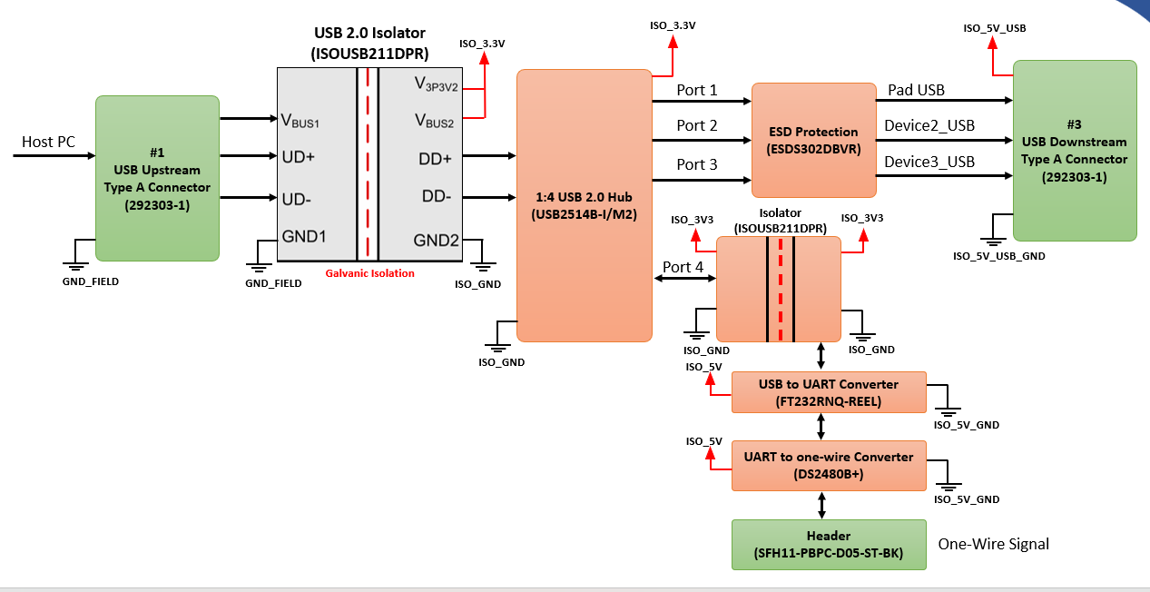
image.png


Regards,

Abhishek

  • Hi Abhishek,

    Thanks for reaching out and providing detailed 

    For the isolated side supply, please confirm whether it is preferable to use a 3.3 V rail generated from an isolated DC-DC converter or from the on-board 3.3 V LDO.

    An LDO is always the preferred and recommended approach for cleaner supply to ISOUB211 as well as other devices as well. The noisy supply from DC-DC can affect the signal quality.

    Additionally, for the downstream USB connectors, an isolated 5 V supply has been provided to prevent interference with on-board circuitry

    I'm assuming that this 5V supply is what is getting used for USB to UARD and UART to One-Wire converters supply, correct? - This approach seems 

    If that is the case, then why is the second ISOUSB211 has same supply (ISO_3V3) and ground (ISO_GND) connections on Side1 and Side2.

    Please attach a revised block diagram with correct Ground Names and Supply Names for us to review once more.

    Regards
    Varun

  • Hi Varun,

    In the current design, two separate isolated DC-DC converters are used to generate 5 V rails, as per the customer requirement for a dedicated isolated power supply for the downstream USB ports.

    For the second ISOUSB211, the USB hub is planned to be powered from the isolated 3.3 V rail generated by the isolated DC-DC converter. The second isolator has been introduced to ensure that any spike or transient on the one-wire interface does not propagate back to the USB hub or affect the other downstream USB ports.

    Kindly advise on the recommended approach for supplying power and referencing ground for the second isolator (both primary and secondary sides), so that the block diagram can be updated accordingly and shared for review.

    Regards,

    Abhishek

  • Hi Varun,

    Please find the attached updated block diagram.

    Regards,

    Abhishek

  • Hi Abhishek,

    Can you please reattach the block diagram? - It's not visible in your previous response.

    Regards
    Varun

  • Hi Varun,

    Please find the block diagram below

    TI USB Hub design query.pptx

    Also, can USB type A connector can be used on the upstream ports for receiving data (device interfaces) from host PC.

    Regards,

    Abhishek

  • Hi Abhishek,

    This still does not clarify your system connection. I request you to please be accurate in your block diagram naming of connections.

    For example, the confusion points:

    1. Where did the one_wire_3.3V and one_wire_ground came from in the updated diagram.

    2. Is ISO_5V_GND and ISO_5V_USB_GND are same?

    3. ISO_3V3 and ISO_3.3V are same supplies or different?

    All the above questions are creating a confusion for us to understand your system connection accurately and review it correctly.

    Can you please provide a clean, accurate system connection with power supply and ground nets details correctly depicted for us to review?

    Regards
    Varun

  • Hi Varun,

    Please find the below comments.

    1. One_wire_3V3 will be provided by another isolated 3.3V power supply used for one wire interface only. 

    2. ISO_5V_GND is the ground for the isolated 5V supply used for USB to UART converter and One wire converter IC.

        ISO_5V_USB_GND is the ground for the isolated 5V supply used for only USB downstream ports.

    3. It is a typo ISO_3V3 and ISO_3.3V are same.

    Updated block diagram is attached.

    5554.TI USB Hub design query.pptx

    Regards,

    Abhishek

  • Hi Varun,

    Query:

    Can i use same isolated ground ISO_GND for my all USB interfaces or separate ground like above need to be added.

    Also what are the recommended power supplies to be provided for second isolator, whether can i provide normal 3.3V and ground instead of One_wire_3V3 and ISO_GND. Please provide an advise on the power supplies and grounds

    Regards,

    Abhishek

  • Hi Abhishek,

    First thing - All the grounds on a particular side of ISOUSB connections should be same - Which Means that One-Wire-Ground connection on 2md ISOUSB and ISO_5V_GND on the converter device in invalid. The USB signals need to be reference to same supply and ground between 2 connections.

    Second - for ISOUSB power supply options, detailed explanation is mentioned in the datasheet itself so please refer that under section 7.3.1.

    Regards
    Varun

  • Hi Varun,

    Please find the attached block diagram.

    Does the one-wire_3V3 to be provided from an isolated power supply or any on-board 3V3 can be used?

    8206.TI USB Hub design query.pptx

    Also, can USB type A connector can be used on the upstream ports for receiving data (device interfaces) from host PC.

    Regards,

    Abhishek

  • Hi Abhishek,

    Thanks for the updated inputs.

    The Block Diagram Looks Good.

    Does the one-wire_3V3 to be provided from an isolated power supply or any on-board 3V3 can be used?

    If you have stable 3.3V supply on ISO2_GND plane, then that supply can be used. Just make sure that the supply is capable of delivering High Speed Currents as per datasheet.


    Also, can USB type A connector can be used on the upstream ports for receiving data (device interfaces) from host PC

    Of course, yes, USB type A connector can be used. I don't fully understand your concern with respect to connector though.

    I highly recommend you take a detailed look on ISOUSB211 EVM design as well for your reference during design process.

    Regards
    Varun

  • Hi Varun,

    Thanks for the confirmation.

    In shared block diagram, on the three USB downstream ports, does an isolator is required to protect the Hub from the external transients.

    Please suggest or comment on the above.

    Regards,

    Abhishek

  • Hello Abishek, 

    You can use an ISOUSB211 to protect Ports 1 - 3. The ISOUSB211 is best suited to protect the USB devices from ground shifts. However, the ESD protection is better suited to protect the USB bus from line transients on the bus pins themselves. 

    It is up to you to decide how many protections are appropriate for your application. 

    Best,
    Andrew 

  • Hi Andrew,

    Thanks for the confirmation.

    I want to use the IO expander output signals to enable or disable some of my interfaces. What will be the default state of the output signals (high or low). Does it is recommended to provide pull-up and pull-down resistors for setting the default state of the output pins.

    Regards,

    Abhishek

  • Hello Abhi, 

    ISOUSB211 has integrated pull-up/pull-down resisters. Its default connecting state is described in 7.3.4 Connect and Speed Detection:

    "When there is no peripheral device connected to the downstream side of ISOUSB211-Q1, internal 15 kΩ pull-down resistors on DD+ and DD- pins pull the bus lines to zero, creating an SE0 state. When either the DD+ or DD- lines is pulled up higher than the VIH threshold, for a time period higher than TFILTCONN, the ISOUSB211-Q1 device treats this as a connect. The ISOUSB211-Q1 device configures internal pull-up on the upstream side to match the pull-up detected on the downstream side. After connection is detected, the ISOUSB211-Q1 device waits for a reset to be asserted by the host/hub on the upstream side. Depending on whether DD+ or DD- is pulled up at the start of reset, the speed of the ISOUSB211-Q1 repeater is set. Once set, the speed of the repeater can only be changed after a power down or disconnect event."

    Were you maybe referring to a different device in the signal chain? If yes, please state which device. I can only support the ISOUSB211 device or help with the TI devices in the system. 

    Best,
    Andrew

  • Hi Andrew,

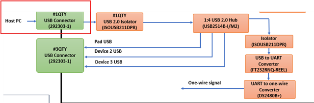
    Below shared in my board USB interface block diagram,

    In this the input USB signal is coming from the host PC through the USB Type-A connector as indicated in the block diagram, then it is passed through the isolator ISOUSB211 and then to the upstream port of the USB Hub. From there out of the four downstream ports, three are connected to the USB Type-A connector and fourth USB is converted into one-wire signal.

    Can USB Type-A connector (marked with red box) be used in upstream ports to recieve the signal from host PC to the USB hub.

    Regards.
    Abhishek

  • Hi Abhishek,

    As I've mentioned this earlier - Yes, USB Type A connector can be used in upstream ports as highlighted above.

    Regards
    Varun