This thread has been locked.

If you have a related question, please click the "Ask a related question" button in the top right corner. The newly created question will be automatically linked to this question.

ISO1540: ISO1540 replace ADUM1250

Part Number: ISO1540

Dear Sir,

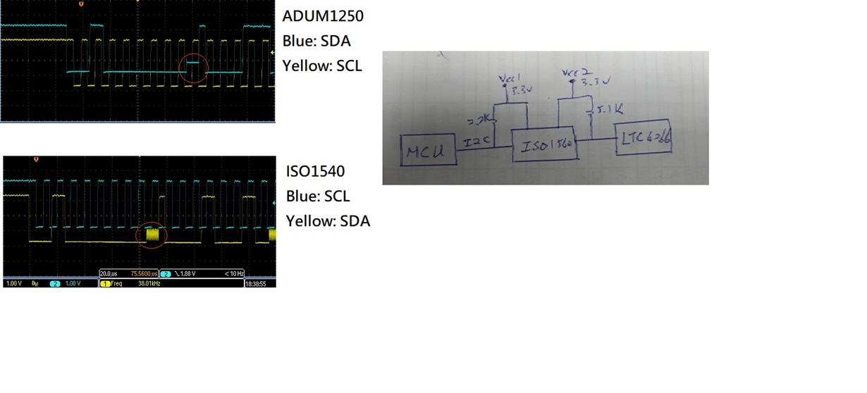
I would use ISO1540 to replace ADUM1250, but face a issue as below waveform

you can see red circle_ ACK signal :

ADUM1250 is very stable -> SMBus OK

ISO1540 have some glitch -> SMBus Fail.

Please you kindly help review & provide some suggestion.

Thanks!

Steven

  • Hi Steven,

    Sorry to hear about the issue.
    We have not seen such glitches on SDA1 of ISO1540 and it is not expected from device either. Can you please confirm the pull-up resistor value for VCC1? Is it 2.2k Ohm? Can you please also share a zoomed-in image showing the glitches?


    Regards,
    Koteshwar Rao
  • Dear Koteshwar,

    Thanks for your respond.

    as picture pull-up resister Side-1 is 2.2Kohm and Side-2 is 5.1kohm, I will update to you when I get customer's waveform.

    Have another suggestion?

    Thanks!

    Steven

  • Dear Koteshwar,

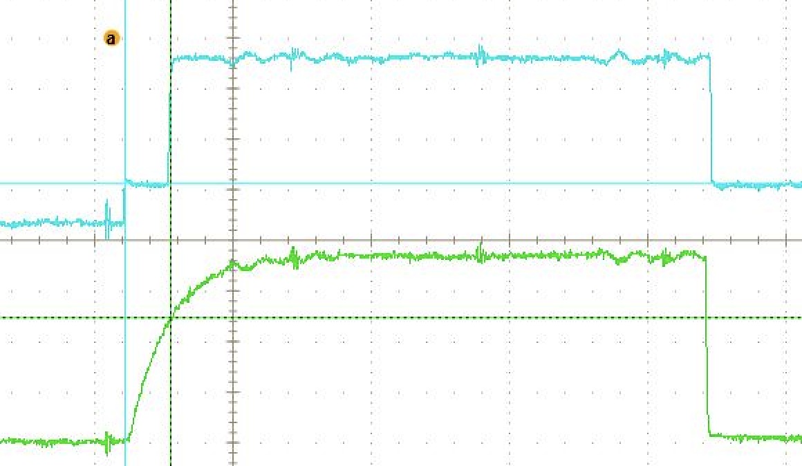
    Please refer zoom-in waveform.

    Thanks!

  • Hi Koteshwar,

    We are working with Steven who is Taiwan TI agent, I doubt that it is related with capacitive load of side 1. How about your thinking?

    Another question, the max of Low-level output voltage(SDA1) that output to master(SoC, PCA9546) is too high(Max 800mV).
    Is it not idea design for SMBus(3.3v application) ?

    Best Regards,

    James Wang
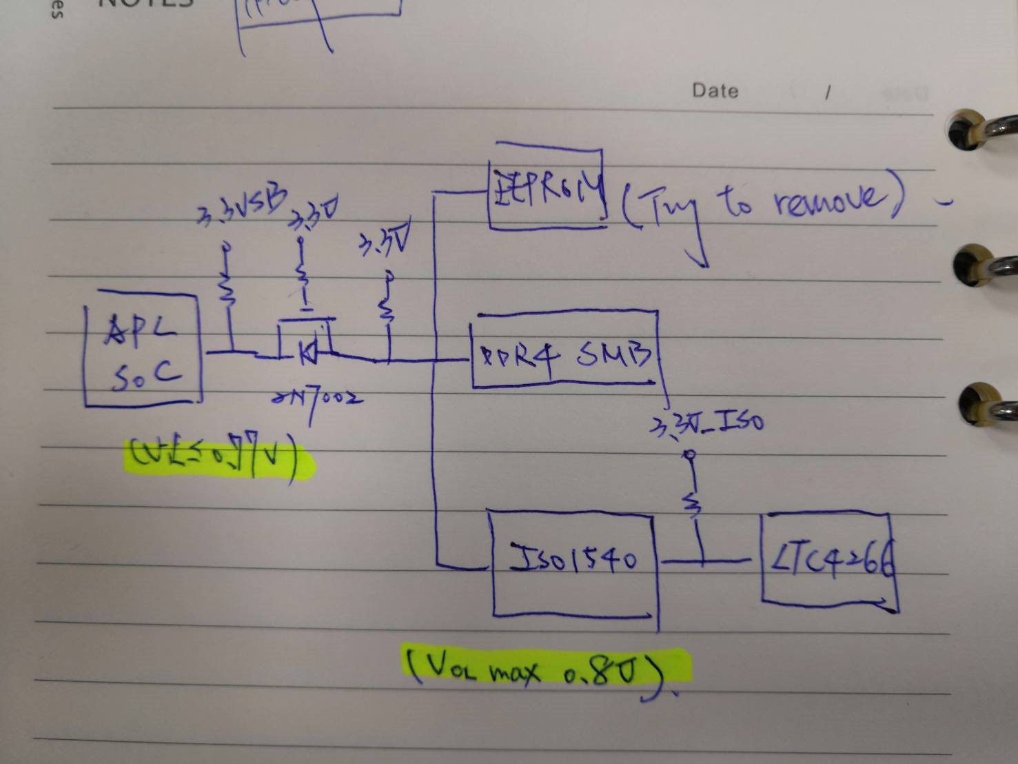
  • More detail for your information. The side 1 of ISO1540 connect to SoC host SMBus by isolated circuit (2N7002) and the SO-DIMM SMB is connect to this.
  • Hi Steven,

    Thanks for sharing the zoomed-in image.

    Hi James,

    Thanks for sharing additional information. I understand your concern on 800mV of VOL1 being more than the usual VOL for TTL/CMOS outputs. Please refer to the FAQ post on this topic at the link below.

    Regarding the ringing observed at SDA1, the device by itself doesn't produce such ringing issue (please see the reference image below). It may be possible an external component is affecting ISO1540. Can you please share the schematic and show the connection between ISO1540 and SoC?

    Regards,

    Koteshwar Rao

  • Hi Steven, James,

    Sorry I accidentally marked it as "TI Thinks Resolved", please help me with the schematic and I can review the same to see if any external component is causing such ringing issue on ISO1540. Thanks.


    Regards,
    Koteshwar Rao
  • Hi Koteshwar,

    OK, understood symptoms occur from most of all isolated parts. We will care the VOL in next project that should be add  divided resistor to avoid voltage to unknown stage.

    SCH as below:

  • Hi James,

    Thanks for sharing the details related to SoC & ISO1540 connection.
    It doesn't look like the MOSFET is causing any issue, did you anyway try bypassing the MOSFET and test? If not, could you please remove the MOSFET and short the trace only for testing / debugging and let me know if it works?

    Meanwhile, I will discuss this with internal teams to see if we can find out what else could be causing such an issue and will come back to you tomorrow.

    One more question, did you see this issue on only one ISO1540 sample or do you find this with multiple samples of ISO1540? Let me know, thanks.


    Regards,
    Koteshwar Rao

  • Hi James,

    I wanted check if you had a chance to remove the MOSFET, replace it with a short and test. This is a good first debugging step.

    I did discuss this with the design team to find out if there is anything in device that can cause such ringing at SDA1. Design team confirmed that when specs are not violated, there is nothing in device that should cause such behavior.

    I did notice one issue with the schematic. SDA1 & SCL1 of ISO1540 only support about 40pF of capacitive load and ideally these pins should only be connected one I2C node (master / slave) while SDA2 / SCL2 can have multiple devices connected to it without any issues and it supports upto 400pF of capacitive load. In your application, it looks like there are three devices (SoC, EEPROM &DDR4 SMB) connected to SDA1 of ISO1540.

    Can you please remove EEPROM and DDR4 SMB and test only SoC with ISO1540?
    Alternatively, if your intention is to isolate LTC4266 from rest of the I2C bus then SDA1 / SCL1 should be connected to LTC4266 while SDA2 / SCL2 should be connected to I2C bus which includes SoC, EEPROM & DDR4 SMB.

    Please do try the above suggested options and let us know if everything works fine. Thanks.


    Regards,
    Koteshwar Rao
  • Hi James,

    I just wanted to check if you had a chance to test the above suggested changes? Let me know, thanks.


    Regards,
    Koteshwar Rao
  • Dear Koteshwar,

    I with customer confirm:  short 2N7002 is OK.

    But have concern why ADUM1250 is OK ?

    If customer could use iso1540 how to avoid this issue, please you kindly provide suggestion.

    Thanks!

    Steven

  • Hi Steven,

    Thanks for the confirmation.
    I would not be able to comment on ADuM1250. From datasheet, I see that both ADuM1250 and ISO1540 have the same capacitive load limits. Hence, my guess would be that ADuM1250 might be working marginally and it is better to avoid this situation.

    The best option is to flip the device and connect Side1 to LTC4266 and Side2 to SoC and other nodes. This should work fine without any issues. Let me know if you have any questions, thank you.


    Regards,
    Koteshwar Rao
  • Hi Steven,

    I wanted to check if customer had a chance to test ISO1540 the way I have described above. If yes, can you please confirm that the waveform look clean now without the ringing that was observed earlier? Thanks.


    Regards,
    Koteshwar Rao
  • Hi Koteshwar,

    Yes, it flipped the device before. It work normally, it is why we talked about capacitance limitation.

    Could you check with your design team about this. Thanks.

    James Wang

  • Hi James,

    Thanks for testing this and confirming that it is working fine when ISO1540 is flipped such a way that Side1 of ISO1540 connects to LTC device while Side2 connects to three devices - SoC, EEPROM & DDR4 SMB.

    This is the correct usage of device ISO1540, Side1 with 40pF load capacitance support should ideally be connected one device that needs isolation while Side2 with 400pF load capacitance support can be connected to multiple devices. I recommend doing this modification on your PCB so that you do not face any issues future. Thanks.

    Let me know if you have any other questions, thank you.


    Regards,
    Koteshwar Rao