This thread has been locked.

If you have a related question, please click the "Ask a related question" button in the top right corner. The newly created question will be automatically linked to this question.

ISO7762: RS485 data getting corrupted

Part Number: ISO7762
Other Parts Discussed in Thread: ISO7731

Hi , 

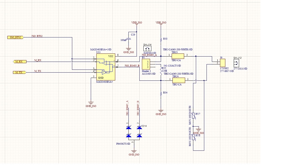
We are using ISO7762F for providing isolation of RS485 communication. Please refer the schematic , We are facing CRC error at the USB to RS485 Transceiver ,we have observed the  waveform very closely & found that only 9Th byte of Received data packets  getting corrupted, any data on that byte is read as "00" . We have also tapped the MCU data , when transceiver is not polling using MBPOL all the data tx & rx before & after ISOLATOR are read correctly. however when we start polling using MBpoll CRC error persist. 

We have tired changing USB to RS485 transceiver still CRC error remains same. We can share gerber file if needed. 

Please help me for the same. 

Gaurav 

  • Hi Gaurav,

    Sorry to hear about the issue and thank you for reaching out to us.

    I am assuming the datarate of signal applied at TX and RX is not very high. You also mentioned of USB to RS-485 converter, seems like you have an RS-485 to USB converter connected at the RS-485 port shown in the schematic above.

    Since there are about three devices between the MCU and the USB host/device, the first thing I want to make sure is to check if the issue is due to isolator. For this, I would request you to de-solder device ISO7762 from PCB and short the connection assuming this has no impact on product functionality while debugging. Once the isolator is bypassed, please check again if you still see the CRC error. Please update us once you are able to run this test.

    In ISO7762 schematic, I do not see the decoupling capacitors populated. Can you please confirm if the decoupling capacitors are not visible in the schematic or if they are not used at all. It would also help if you can share more detailed schematic and PCB layout gerbers. Thanks.


    Regards,
    Koteshwar Rao
  • Hi , 

    I have tired the above suggestion , when there is no ISO7762F it works just fine when it goes to original circuit i face the issue. Please find sch & gerber in the below mail. please suggest , we have done various trial & error, We have made discrete isolator board ( Using instead of using FODM8061) ISO7762  it works just fine. 

    Gaurav 

    MSPL-PD-GRB-MSAT200-R00.zipMSPL-PD-TRCK-RA001.pdf

  • Hi Gaurav,

    Apologies for the delay in my response, I missed out to come back to you on this one.
    Thanks for trying out the experiments to see removing ISO7762 makes any difference, I am not quite sure why there is only 9th byte error.

    I noticed that there are no dedicated decoupling capacitors for VCC1 and VCC2 of ISO7762 but I do see there are C27 (4.7uF) and C28 (10uF) capacitors shared between U10 (ISO7762) and U9. It is highly recommended to have 0.1uF capacitors between VCC and GND as close as possible to device pins. Hence, I recommend you solder one 0.1uF capacitor on top of C27 and C28 and test again.

    Since you only need 3 channels, using ISO7731 or ISO774x will make you VCC/GND pins available right next to each other enabling you to keep the decoupling capacitors as close as possible to both the pins. Anyways, please try out adding the above mentioned decoupling 0.1uF capacitors on top of C27 and C28 and check if it addresses your issue. I am not quite sure if this is the problem but I do not see any other issues. Thanks.


    Regards,
    Koteshwar Rao
  • Hi Gaurav,

    Just wanted to check with you if you were able to try out the above experiment and if the issue is resolved? Please do let us know your inputs so that we can help you further. Thanks.


    Regards,
    Koteshwar Rao
  • Hi Gaurav,

    I am hoping that you were able to resolve the issue, I will go ahead and mark this E2E thread closed. If you still have questions, you can reply back to this post or create a new E2E post. Thanks.


    Regards,
    Koteshwar Rao
  • Dear Mr.Rao , 

    The above suggestion did not solved the issue so previously we were using ISO7762F & then we replaced it with ISO7762 , it is working fine now , However thank you for your support . 

    We have given go ahead to our EMS vendor for its mass prdouction . Again Thank you 

    Warms Regards 

    Gaurav Valecha 

  • Hi Gaurav,

    I am glad to know that you were able to address the issue and proceed with the design for mass production.

    We typically do not expect any communication issues whether ISO77xxF (default LOW) or ISO77xx (default HIGH) in used for any communication interface. The default state is only going to make a difference in choosing the bus default state. Some communication interfaces may need the bus to be in HIGH state when there is no communication, that's where the isolator default state comes handy.

    In your application, it maybe possible that the input pin of isolator is intermittently left floating which may have lead to a default state at the output. This could have been the reason for seeing seeing an incorrect CRC. If the input pins of ISO7762F were to be continuously driven, we expect the output only follow the input and not cause any issue. It seems like for your implementation a default HIGH state device suits better.

    Thanks again for working to address the issue and continue using the device.


    Regards,
    Koteshwar Rao