This thread has been locked.
If you have a related question, please click the "Ask a related question" button in the top right corner. The newly created question will be automatically linked to this question.
Hello,
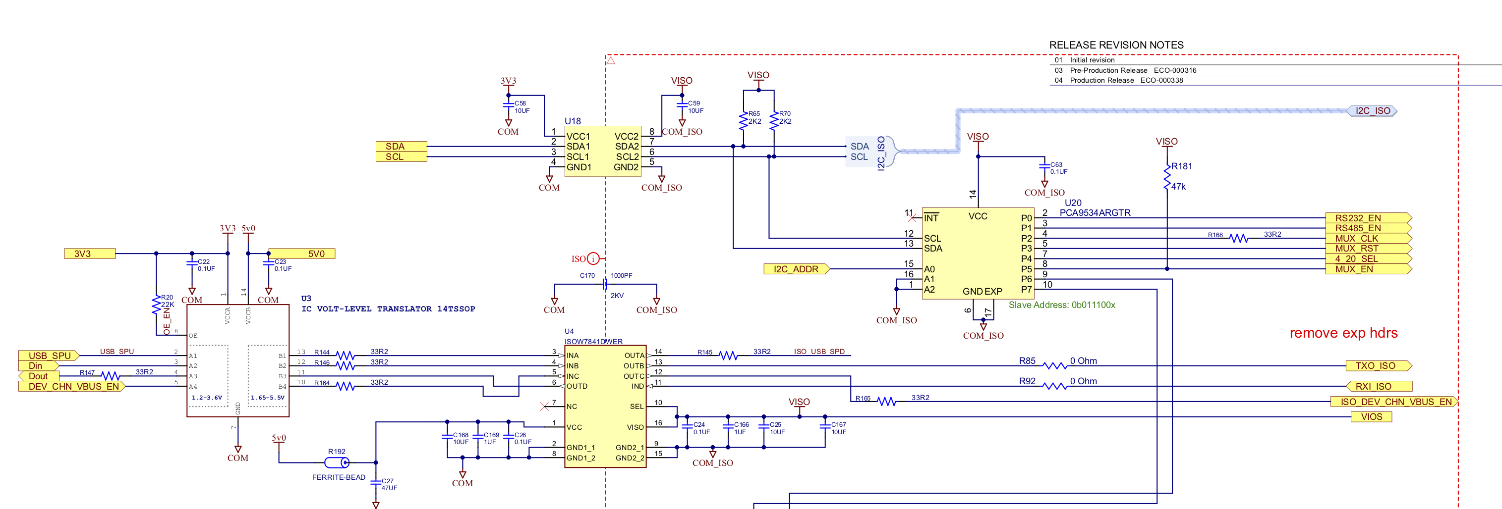
We have units in the field that are failing. In circuit I measured Viso as 1.965V and the chip is very hot. So first thought is that the circuit is shorting the output of the ISOW7841. However, I lifted the VISO and VSEL pins on the ISOW7841 and powered the rest of the isolated circuit from a lab power supply and measured 18mA at 5V. So I don't think it's the isolated circuitry.
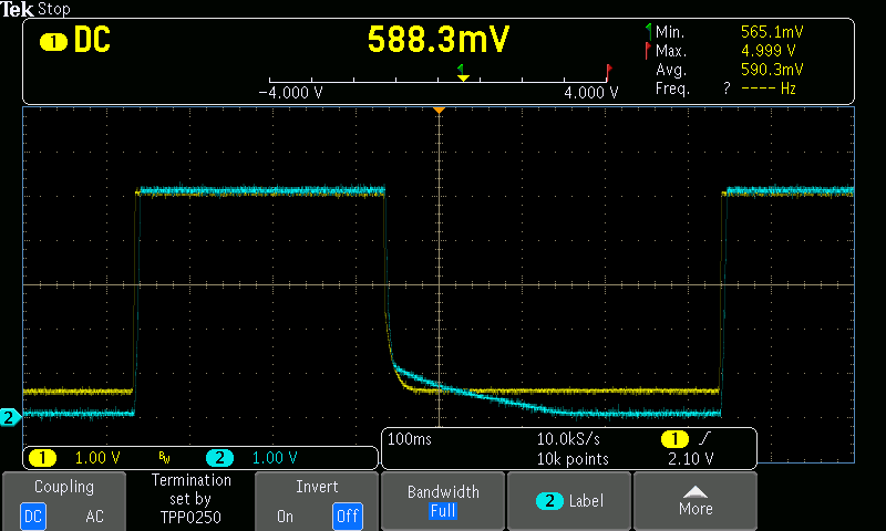
Next I measured the output of the ISOW7841, open circuit and with a load consisting of 1000uF & 100 ohms (50mA). Scope traces are attached.
It's obvious that the ISOW7841 is NFG, but what could cause this issue? I can send your team the IC if needed for further analysis. I ordered replacement ICs and will swap out the part once the replacements arrive.
Input voltage is 5V and VSEL is connected directly to VISO for 5V output.
On the input side of the ISOW7841 there is 47uF || 10uF || 1uF || 0.1uF. On the VISO output side there is 10uF || 10uF || 1uF || 0.1uF.
The 5V rail that is powering this chip (and the attached voltage translator) gets powered up about once every 15 minutes, does its thing, and then gets turned off. I measured the slew rate of the input power as 1mS/V and it is smooth, well within the 10mSec parameter on the datasheet to get to full 5V. The voltage translator is a TI TXB0104, bidirectional. One thought is whether the translator is to blame, but I couldn't figure out how that could cause VISO to fail.
Thank you,
Derek
Hi Derek,
Thank you for posting to E2E! It is possible the ISOW7841 Viso output is damaged, and that's why the output is clamped at <2V. This could be from ESD or overvoltage stresses, which is uncommon for ISOW78xx devices.
In order to prevent such damage, we typically recommend following the guidelines from Section 11 of the ISOW7841 datasheet. It is possible there is some discrepancy between Viso and Vcc_in UVLO circuits or the input current limit is too low. In these cases, increasing the capacitance on the ISOW7841 power supply input to be at least 100uF greater than the capacitance on Viso should help prevent the damage as mentioned in the two related threads I've linked as references below:ISOW7841: ISOW7841DWER damage question - Isolation forum - Isolation - TI E2E support forums
ISOW7841: Secondary side power output (VISO) issue - Isolation forum - Isolation - TI E2E support fo...
Please let us know your thoughts!
Thank you,
Manuel Chavez
Thanks, I'll look through those links.
If one of the logic inputs/outputs gets stressed, could that cause the DC-DC Viso output to be like this?
Could the bidirectional level translator be to blame, during startup or shutdown?
Hi Derek,
No problem! Stress on I/Os could cause Viso to behave this way, but it is not likely. The device also uses a differential signal pair to communicate HIGH/LOW signal levels across the isolation barrier, so signal level translation happens locally and independently of each power supply.
Most likely the issue is occurring due to a startup or transient discrepancy between Vcc1 and Viso, where the device is not able to correctly determine whether Viso is at the appropriate level or not. This would be similar to the 2nd related thread linked above.
Respectfully,
Manuel Chavez
Hi Derek,
I will support you with this issue on behalf of Manuel.
Sorry to hear about the issue again and this issue does seem quite different which I have not seen before. Could you please help me with the answers for following questions?
Regards,
Koteshwar Rao
1. I removed the cap so the load is only 100 ohms, it is now a rather perfect square wave, 262.5kHz, same as before.
2. Agreed
3. VSEL (pin 10) is connected to VISO to configure for 5V operation. I also tried connecting VSEL to GND but the output remains the same.
4. Waveform of first image (perfect square wave) is with only 100 ohm load. Second waveform is with the 1000uF cap on the output.
5. We have seen this on only one device. On another device we have a bad GPIO expander (u20 in the schematic provided). However, it appears that the isolator in that one is still working properly. Is it possible that the isolator is malfunctioning and causing overvoltage? I know the Analog Device version of this chip has this problem.
Also, I have the IC here and can send it to you for further analysis if needed.
I am setting up a test for other boards whereby we toggle the input power to the isolator once per second to try to duplicate the problem.
Thank you,
Derek
Found another unit with a similar issue. Voltage into the ISOW7842 is nice 5V but output is a constant 785mV. The IC is warm but not super hot.
Update:
We tested five boards. Each has two channels (named DP1 and DP2) of ISOW7841. Test consisted of turning on the 5V to the isolator for one second, and then verifying that the voltage coming out was good. Then it turns off power for one second.
Unit 0: Original batch of boards, nothing changed on it at all. Ran 172k tests and passed. This is the only one.
Unit 1: This is the unit that had the square wave output, so I removed the ISOW7841, then measured current on the VISO load. It was 18mA, so no short there. Then (with the chip removed) I powered the isolated side from a bench power supply; everything worked ok. I put a new ISOW7841 part in, and ran the test. Ran 63k times and still running.
Unit 2: Failed after 30 tests on channel 1. VISO is 0.78V continuous. Removed isolator, verified that the isolated section current is normal and everything there works, and installed a new ISOW7841. The test stopped after 9400 tests because the second channel (with original chip) failed. So I restarted the test with only the updated chip. Still running, 8400 tests and counting.
Unit 3: Upgraded input capacitor from 47uF to 100uF. Failed test even once.
Unit 4: Upgraded input capacitor from 47uF to 100uF. Failed after 87 tests. Output is only 3.53V and the ISOW7841 is quite hot.
Units 5 & 6: ISOW7841 working but the TI GPIO expander is not responding over I2C. Other I2C peripherals on isolated side work fine.
Attached image: top IC is the one I pulled from the board that did not work. (Lot code 93APZXT, CM purchased from Digikey a couple months ago) Legs are a little bent because I first tried lifting the legs while troubleshooting.
Bottom IC is brand new purchased from Digikey last week before I installed it. Lot code 88AGN5T.
Since this is now regarding more than one part, I moved this to its own thread, see "
Hi Derek,
Thank you for sharing these updates. The team is discussing this behavior internally, and we should provide a response on this as well as on the new thread in 1 - 2 days.
I apologize for the delay.
Respectfully,
Manuel Chavez
Hi Derek,
Apologies again for the delay from our side in coming back to you. I will respond to your other new thread and we can continue the discussion, thanks.
Regards,
Koteshwar Rao
Hi,
This discussion has moved to private e-mails to look deeper into system and debug the issue. Once we reach a resolution, will come back and post an update with a summary. Thanks.
Regards,
Koteshwar Rao