This thread has been locked.

If you have a related question, please click the "Ask a related question" button in the top right corner. The newly created question will be automatically linked to this question.

RF chip that can demodulate/separate (multiple) orthogonal signals ?

Other Parts Discussed in Thread: CC1120, CC1101, CC1190

Hi 

I have been looking for some RF chip (such as CC series .... or some other one) that can do multiple orthogonal signals separation

For example, for the RFID application,

tag A (using an RF chip) to send signal A

tag B (using an RF chip) to send signal B, and A is orthogonal to B (probably A and B is CDMA signals)

reader C (using THE RF chip that can separate orthogonal signals) can give output of A and B separately.


Do you know about , any RF chip can do this ?

As far as I know, its seems that the CC seriers do not provide this function (am I right ?)

Thank you very much

Bob

  • At least for the CC1120 it is possible to get the raw data from the ADCs in the I and Q path out on pins. Does this help you?

  • Hi 

    Thank you so much for response ! It is good to know that the raw I/Q information can be output.

    Further question: Is this I/Q raw data corrupted by the channel or not ? (That is, is channel equalization done yet or not ?)

    I guess it is still corrupted by the channel (which is a good thing, is what I want)


    For example, 

    the original signal sent by transmitter is A=+1, and the channel is C (a complex number, like C= +1.4 - 0.7j).

    I guess here the raw I/Q data that CC1120 output would be I=+1.4 and Q = -0.7.

    Is it ?


    If it is, though CC1120 does not separate orthogonal signals, I can utilize the raw I/Q data , and try to extract the independent information of the two transmitters (A and B, respectively), by way of some programming, maybe.

    Thanks

    Bob 


  • Information about the CC1120 you can find here: http://www.ti.com/product/cc1120

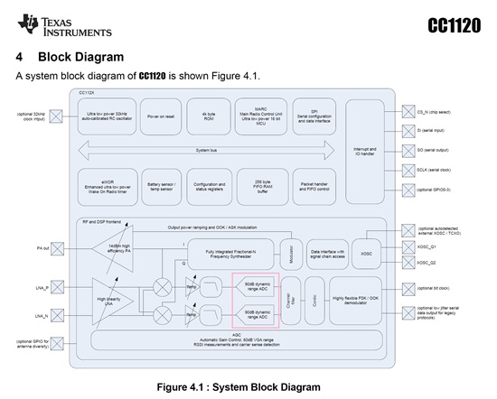
    On page 20 in the datasheet it is a simplified block diagram over the chip. The RF signal is amplified in the LNA, splitted in a I and Q path by a mixer and further amplified before entring the ADCs. The gain in both the LNa and the IF amp is variable but no processing on the received signal is done before after the ADCs. For your application you have to do your own signalprocesing/ demodulation on the raw data to be able to extract the data you are interested in.

  • Hi 

    Thanks a lot for the response.

    We checked the data sheet you mentioned, yes it is very helpful.

    TWO Further detail questions:

    1, From which PINs can we get the raw I/Q data ?

    2, Is the I/Q raw data digital data or analog data ?

    There are LPF0 and LPF1 PINs, and they should be Low Pass Filter output PINs. From the diagram on Page20, the two PINs are before the ADC. 

    So I guess, if these two PINs are the only PINs that can output raw I/Q data, they output analog data. Right ?

    Are there some PINs right after the ADC, to output digital raw I/Q data ? 


    Thank you very much 

    Kind regards

    Bob

  • According to the user guide, table 8, the I and Q data could be output on GPIO2 and GPIO0. This is the data directly from the ADC outputs.

  • Hi

    Thanks a lot.

    I've checked the user guide "swru295.pdf" very carefuly, and yes the Table 8 describes GPIO.

    However, it does not assure that the output of of GPIO is "the I/Q raw data" "after ADC".


    In Table 8, it describes the GPIOx_CFG 0, that :

    Associated to the RX FIFO: Asserts when RX FIFO is filled above 

    FIFO_CFG.FIFO_THR. De-asserts when RX FIFO is drained below/equal 

    to FIFO_THR.  


    Best Regards

  • Table 8 (page 19), decimal 46: ADC_DATA. This is the raw data.

  • Hi

    Thanks again for your response.

    So these are probably the last questions:

    Does CC1101 support this function of outputing soft values ? (Cause we already bought CC1101, that is, actually, CC430)

    Does this kit http://www.ti.com/tool/cc1120dk give soft values output of CC1120?  (Yes we checked the datasheets and userguides of the kits, but still need to double-check. Thanks for your help) Or any other kit for CC1120 you may recommend ?

    Kind regards

    Bob

  • On the CC1101 it is possible to output the raw data as a serial datastream:

    Copied from the CC1101 datasheet:

    GDO0_CFG[5:0]
    GDO1_CFG[5:0]
    GDO2_CFG[5:0]
    Description

    16 (0x10) ADC I/Q – serialized

    I have to check which format this datastream has and if CC430 has implemented this.

    It is possible to get the raw data from the CC1120 DK. The GPIOs are routed out on a pin header on the TRXEB.

  • Hi

    Thank you very much for your former responses.

    Some more questions below .......


    1st, We've bought the TrxEB (CC1120 DK) and did some tests. From the GPIO0 and GPIO2, some wave is output, and it looks like digital 0 or 1 signals. However, we do not know how to recover the original raw I Q data from these 0 or 1 sequence. We guess: the output is the coded 01 sequence of  the ADC output. For example, if the original analog signal is pi, while the sample is 3.1415926,  the ADC quantizes it into 3.14 (get rid of  the rest part, 0.0015925), and then encode this 3.14 in to some 01 sequence -- this encoded 01 sequence is the output of the GPIO0 and GPIO2. So, if our guess is right, how do we recover the value 3.14 from the observed 01 sequence output from GPIO0&2. 


    2nd, Where may we find the brochure of this ADC, and detailed explaining of the CC1120 chip ?


    3rd, Where may we find the detailed information of the other blocks besides ADC of CC1120 ?

    The user guide and datasheet of CC1120 is not detailed enough, for example, there is no information about each block,

    --e.g., the ADC: how many bits this ADC is ? what encoding scheme this ADC use ? Is there a preamble or synch word at the start of each encoded symbol ? and so on.

    --e.g, the channel filter : is this a low-pass channel filter ? Or Is this a match filter to do equalization ? and so on.

    and the other blocks

  • It is limited how much information we give on the external building blocks.

    The ADC is a single bit sigma delta so a bit stream represent a symbol. For test purpose you should take the stream into Matlab and low pass filter it there to recover the original data. Start by applying a sine wave and see if you can recover that from the ADC data.

    If you use the ADC data those are output before the channelfilter.

  • Hi 

    Thank you very much again, for your answer and patience.

    We still have some questions ....  :

    Can you please let us know what is function of the channel filter, and that of the Cordic (we have knowledge about these though. But the questions still have to be asked because in some scenarios people refer to different concepts by the same terminology) ?  In other words, what kind of signal is output from the channel filter and Cordic ?

    -- If there is some detailed documents we can read about those blocks of CC1120, that is the best.

    I guess what we need may be as simple as: the output of the channel filter (if the channel filter functions just as a low pass filter) ; or may be the output of the Cordic.


    Thanks

    Bo

  • Hi

    Thank you very much for your former responses and your help. We really appreciate.


    Now The problem is like this: we always get the same output from the receiver, regardless the transmitter is on or off. 


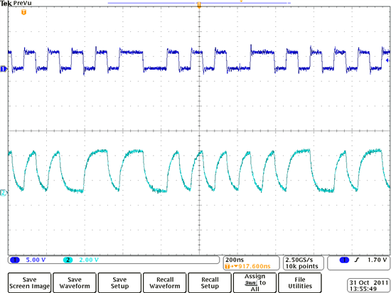
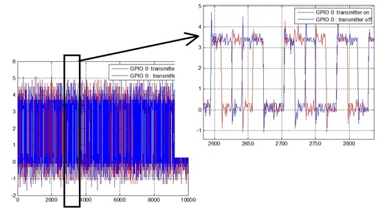
    The image from Oscilloscope. The transmitter is on, this image shows what the receiver get from its ADC output.


    The image from Oscilloscope. The transmitter is off, this image shows what the receiver get from its ADC output .

    (Even we tried this test in the shield room where there is no interference, we still got the same result)
    Details of configurations: we use SmartRF studio and CC1120DK (two boards), and make "IOCFG0 = 2E, IOCFG2 = 2E, " according to the Table 8 of CC112X user guide, as the attached PPT shows:
    Best regards
    Bo
  • Note that SmartRF Studio uses some of the IOs when in "continuous Rx" (IOCFG2) and "package Rx" (IOCFG2 and IOCFG0). If you are using one of these options you probably are monitoring the wrong signals.  To have full control over the IOs, use the "RF Device Commands" tab and send the SRX strobe to put the chip in Rx.

  • Hi

    Thanks for your former response. May I have more questions please 


    1st --- 

    We tried all the three modes "continuous Rx", "package Rx"  and "RF Device Commands" , but the output of GPIO0 and GPIO2 are all the same for these three modes.

    Regardless the transmitter is on or off, the receiver always get the same thing from GPIO0 and GPIO2 for these three modes. (as the pictures of yesterday, from oscilloscope)


    2nd --

    Should the IOCFG to be configured as "2E" (to make GPIO output the raw ADC data) ? -- as the powerpoint file uploaded yesterday ?


    3rd --

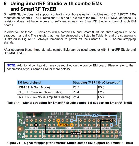
    Does SmartRF NOT support CC1120 ? Should we strap some signals manually before using SmartRF with CC1120 ? (as follows, the Page 21 of swru294)


    Best regards

    Bo

  •  

    Hi

    Thanks for your former response. May I have more questions please 


    1st --- 

    We tried all the three modes "continuous Rx", "package Rx"  and "RF Device Commands" , but the output of GPIO0 and GPIO2 are all the same for these three modes.

    Regardless the transmitter is on or offthe receiver always get the same thing from GPIO0 and GPIO2 for these three modes. (as the pictures of yesterday, from oscilloscope)


    2nd --

    Should the IOCFG to be configured as "2E" (to make GPIO output the raw ADC data) ? -- as the powerpoint file uploaded yesterday ?


    3rd --

    Does SmartRF NOT support CC1120 ? Should we strap some signals manually before using SmartRF with CC1120 ? (as follows, the Page 21 of swru294)


    Best regards

    Bo


  • 1) and 2): Before I sent yesterdays answer I checked that it worked. I used the "RF device commands" tab, sat IOCFG2=IOCFG0=0x2E and connected a logic analyzer to the GPIO2 and GPIO0 connectors on the TRxEB. Then I got a signal out when I strobed RX, not when I strobed TX or Idle. I get different result each time I stobe SRX which is consistent with receiving noise. Even when the transmitter sends a modulated carrier the bits sent out on GPIO2 and GPIO0 will be different each time SRX is strobed due to the nature of a sigma delta.

    3): Strapping is not required. This is only used in some cases where you have a board with CC1120+CC1190 and want to control the required control signals on the CC1190 from the MSP and not from CC1120.

  • Hi TER

    Before we redo the experiments very carefully again (and we will try every possible ways we can think about to get the right result), I must say "thank you very much", for taking this seriously and helping us with so many efforts. Your efforts and testings have shown that at least our group is following the right way ( going the right direction ).

    This really means a lot to us. Our project may turn out to be a big deal, and we may use large number of TI CC1120 chips in near future if we can make our project which is a 1-3 years project that is expected to lead to products commercialization. 


    Kind regards

    Bo and our group

  • Hi

    Thanks for your former responses.

    We carefully repeated the same testing, and get the same result as yours, that is: GPIO does output nothing when STX is strobed. The GPIO does output something when SRX is strobed and it outputs different waves each time. 

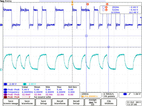
    However, the wave it outputs are actually the same type regardless the transmitter is on or off, when SRX is strobed. We expected to get some signal from receiver's GPIO when transmitter is on, and no signal (or another totally different type of signal) from receiver's GPIO when transmitter is off. But regardless the transmitter is on or off, the output of GPIO is still the same "type". That is, from the output of GPIO (the oscilloscope), people cannot tell whether transmitter is on or off. -- This can not be right.

    Please see the output of GPIO as the pictures below:

    This above picture is the output of GPIO/oscilloscope when transmitter is off, SRX is strobed on the receiver.


    This above picture is the output of GPIO/oscilloscope when transmitter is on , SRX is strobed on the receiver.

    (we used a very good signal generator as the transmitter, and when the signal generator is on, the RSSI jumps up on the receiver which means the configuration of the signal generator is right.)


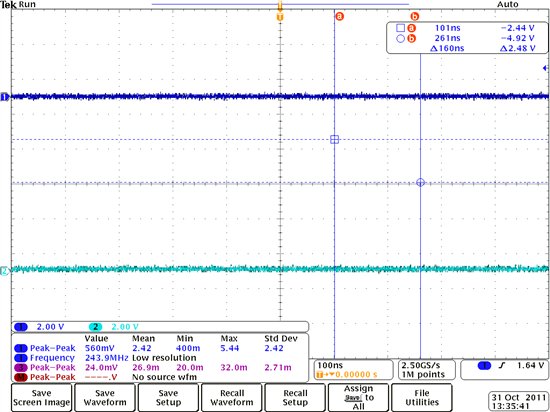
    This above picture is the output of GPIO/oscilloscope when STX is strobed on the receiver.

    Thank you very much for all your help and efforts. We really appreciate it.
    Bo and our group.
    PS: we are really anxious about this test, and we have tried over a month in here. Is there some other way we can try ? EMAIL : hongbog@ece.ubc.ca


  • Is it possible to probe before ADC ?  (That would be really helpful)

    Thanks

  • Please keep in mind that a sigma-delta converter achieve good resolution by shaping the quantization noise. For a conventional ADC with n-bit output the noisefloor (quantization noise) vs frequency is flat. For a low pass sigma delta modulator the quantization noise is shaped so the noise energy is much larger on high frequencies than in low. Hence a sigma delta ADC contains of two parts(simplified): A  modulator and a lowpass filter. The modulator shape the noise and the filter removes the noise at the frequencies of no interest. The bit stream out from CC1120 is the output of the sigma delta modulator. Even with no input to the modulator will shape the quantization noise and the result is that the bit stream is not a stream of '0'. It is not possible to see from just a few samples of the bit stream what the input signal to the modulator is. To see this you either have to lowpass filter the stream or run a FFT on the data (in the simulations I did I used at least 6000 samples). Hope this makes it more clear, sigma-deltas is not straightforward.

    Also note that you will lose ~10-15dB in sensitivity by using the GPIOs to output the data due to the noise the pads introduce. An alternative is to output the data on the LVDS interface (not documented but used in the lab with no decline in sensitivity). The datastream on the LVDS interface is clocked at 2xcrystal frequency and has to be oversampled in the receive side adding cost and current consumption.

  • Hi

    Thank you for the response again. Still more questions .... 

    ADC has three blocks: sample, quantization, coding. Let say an input analog signal is pi, then after sample it is 3.14159, after quantization it is 3.14, then after coding it is 1000100... (n bits), which is a 0/1 bit stream. I trust this 0/1 bit stream is the output of the output of GPIO or ADC. 


    1, Now that we can trust the output of GPIO is the ADC output of the raw data, which is a 0/1 bit stream, how to decode this bit stream ? Information about the ADC is needed. For example, this is n-bits ADC, then how large is this n ? What is the sample rate ? How to find the start of each sample (suppose each sample is quantized into n bits.) ?

    2, How to lowpass filter the output of ADC ? I mean, do we input the bit stream into a low pass filter ? Or do we first decode the bit stream (decode it back to a sample of the transmitted MSK symbol) and then input the decoded sample stream into a lowpass filter ? -- Another expression of this question could be : how does the channel filter in CC1120 work ? 

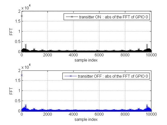
    3, Similar as question 2, I tried directly perform FFT on the output of GPIO, but this seems not make sense, since this output of GPIO is not the sample of some signal. It is a 0/1 bit stream which comes from of the quantization of the sample of TX signal. The 0/1 bit stream is not supposed to be directly done by FFT (The figures below:)

    The above figure is the output of GPIO 0 (Transmitter ON and OFF)


    The above figure is the FFT of the output of GPIO 0 (Transmitter ON and OFF -- they are the same ?!)


    ---------------

    If there are some manuals regarding the ADC , the channel filter, the cordic, the demodulator, that would be most helpful.

    Best regards

    Bo

  • "ADC has three blocks: sample, quantization, coding. Let say an input analog signal is pi, then after sample it is 3.14159, after quantization it is 3.14, then after coding it is 1000100... (n bits), which is a 0/1 bit stream. I trust this 0/1 bit stream is the output of the output of GPIO or ADC. "

    Yes and no. As I have written before the ADC is a single bit sigma delta modulator with Xtalfreq/2 sample rate. From what you write I get the impression that you are not too familiar with sigma-delta modulators, please correct me if I'm wrong. If you haven't used one before, please look at the "delta Sigma Toolbox" (http://www.mathworks.com/matlabcentral/fileexchange/19) that will give you some insight in how they work. The book Richard Schreier has written on the subject is also a good intro. You should also be able to use some of the functions in the toolbox to run FFT on the datastream and plot it in a more readable format than you have used. When plotting the spectrum from a sigma-delta it is normal to plot dB (20*log10() ) on the y axis and use a logaritmic x axis.

  • Hi 

    Thanks a lot for all the former responses. We have been always watching the responses and thinking/doing_testings accordingly.

    Our target is to utilize the output of ADC "raw data" to recover the input of ADC (and do some DSP by MATLAB), so besides learning thoroughly this sigma-delta ADC thing (we are learning it and we realized that we must learn it seriously so as to make good use of the output of the ADC of CC1120), I guess we also need some more information or parameters:


    1, what is the IF frequency ? (say, 1MHz, or 100KHz ?)

    2, Sampling rate of the sigma-delta ADC

    3, the center frequency of the channel filter


    In short, is it possible to have the datasheet/user_guide of each block ( or,  at least the datasheet/user_guide of this ADC) of the CC1120 ? Cause the datasheet/user_guide of CC1120 itself (i.e., swru295   and http://www.ti.com/lit/ds/symlink/cc1120.pdf) does not provide much information regarding the ADC.

    Thanks

    Bo and our group


  • Hi 

    On the CC1120DK (TRxEB),

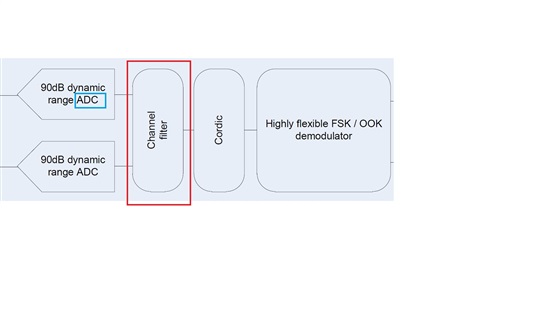
    is there some PIN to get the output of the channel filter ? (In CC1120 block diagram, its channel filter is after ADC


    I suspect the channel filter of CC1120 functions as the filter&decimator as depicted in the dash line box below:

    Thanks


  • 1, what is the IF frequency ? (say, 1MHz, or 100KHz ?)

    See 9.2 in the UserGuide.

    2, Sampling rate of the sigma-delta ADC

    See my previous post.

    3, the center frequency of the channel filter

    The center is the IF frequency

    We don't have a supported way to output data after the channelfilter on a GPIO


  • Hi

    Is it possible to make CC1120 send QPSK or BPSK signal ?

    --Though according to the userguide and datasheet, the only available signal, which is close to QPSK, is MSK.


    Thanks

  • Hi 

    Thanks for your former responses.

    We have problem in filtering the output of ADC (that is, the output of GPIO).

    Is there anyway to get/buy this digital bandpass channel filter , such as from TI ?

    Thanks a lot

  • No,

    you have to use a MCU, FPGA or DSP with suffisient processing power and implement the filter in software.

  • Hi TER,

         More queston abot I/Q output: 

          Q1: Can I have I/Q data reading out from the CHFILT_Ix ( x= 0,1,2) and CHFILT_Qx (x= 0,1,2) registers instead of from GPIO0/GPIO2 ?  What clock rate for these registers is running on? What is maximum data rate for reading these registers out?

         Q2: Is it posible routing out the CHFILT_Ix ( x= 0,1,2) and CHFILT_Qx (x= 0,1,2) registers contents to output pin in CC1120?

         Q3: What is difference between ZERO-IF and LOW-IF ?

    Robert Lin

  • 1) Yes, the registers are updated with a rate of 4*RXFIlterBandwidth. Note that it is possible to have a signal out on GPIO that strobes when valid data is in the registers, see table 10 in the userguide.

    2) Only if you use the LVDS interface

    3) Low IF is used for low datarates and zero IF is used for high datarates.

  • Hi TER,

             Thank you for answer. Next step, we are going to use CC1120 I/Q output to ingreate with our exsiting baseband board for verification.So we need to you help to clarify how to use them. As you answer, "it is possible to have a signal out on GPIO that strobes when valid data is in the registers, see table 10 in the userguide."

               Here are the questions:

               Q1: What configuration that is need to configure for strobes signal to output from GPIO ? (Strobe by falling or raising edge) 

                      Is it CLKEN_SOFT[IOCFGx.GPIOx_CFG = 29] , SOFT_TX_DATA_CLK [ IOCFGx.GPIOx_CFG = 30], or other ?

               Q2: Where is the LVDS interface in CC1120 ?

    Thanks,

    Robert Lin

  • Hi Robert

    Send me an email if you are interested to discuss/talk with me. I can send you my tel number through email.

    had been working on the I/Q ouput (i.e., GPIO) for months when I was making my prototype using CC1120 board.

    Maybe I can help you a little bit.

    integrghb@gmail.com

    Bob Guo

    Robert Lin2 said:

    Hi TER,

             Thank you for answer. Next step, we are going to use CC1120 I/Q output to ingreate with our exsiting baseband board for verification.So we need to you help to clarify how to use them. As you answer, "it is possible to have a signal out on GPIO that strobes when valid data is in the registers, see table 10 in the userguide."

               Here are the questions:

               Q1: What configuration that is need to configure for strobes signal to output from GPIO ? (Strobe by falling or raising edge) 

                      Is it CLKEN_SOFT[IOCFGx.GPIOx_CFG = 29] , SOFT_TX_DATA_CLK [ IOCFGx.GPIOx_CFG = 30], or other ?

               Q2: Where is the LVDS interface in CC1120 ?

    Thanks,

    Robert Lin

  • Hi Bob,

                Thank you . I will sent  my email address to yout

    Robert Lin