This thread has been locked.

If you have a related question, please click the "Ask a related question" button in the top right corner. The newly created question will be automatically linked to this question.

LSF0101: Up transition levels are not correct

Part Number: LSF0101
Other Parts Discussed in Thread: LSF0108

Hi 

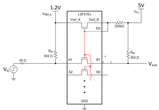
I am working on LSF0108 EVM and powered up the part with VrefA = 1.2 V and VPu = 5V by using triple power supply E3631A . I provided 1Mhz signal from function generator and see the my input levels 0 to 1.2V. The input levels are dropped 0.68V to 1.2V as soon as I connect function generator output to LSF EVM board on A-side and output is ~1.4V to 5V on B-side instead of 0.35V to 5V.   Can you please let me know what is wrong on my setup for UP transition.

Observed that there is relation between power supplies if I sweep the supply Vref-A from 1.2 to 2.7V and high side is also not 5V anymore(dropping from 5V ). Is this expected? if yes my levels are always rail to ref-A when i was doing Up transition.


Regards,

Gopi

  • What is the output impedance of the function generator? When you are using the 300 Ω pull-up resistors, the required drive strength is 33 mA. I'd guess that the function generator cannot output this without a voltage drop.

    With the LSF, the choice of pull-up resistors balances between power usage and speed.

  • I would like to know how you calculated the current 33mA. The pullup voltage is 5V and pull up resistor is 305. so the output current is 15mA on B-side and 4mA on A-side is(1.2V/300). Output impedance of function generator is 50ohm. 1V + 0.375 rise from ground when doing up conversion from 1.2V to 5V. is this correct? What happen when the source is not able to drive the high currents for example in this case is 20mA   How can we minimize these currents(make pull up resistors are large in value) so that all the drivers we can use but it may lower the speed of the signal. My application max frequency is 10MHZ and current drive capability is 10mA . Can you suggest any pull up resistors based on my conditions close to  rail to rail(low side from 0.375V from ground is fine for my application).. 

  • Hello,

    Just to verify, it sounds like this is your setup:

    If V_G is 0V, then we can see that V_REF_A and V_PU are both going to be pulling up the line (because the channel FET is on), and we end up with this relatively simple resistive network to solve:

    The voltage at the output of the generator / input at A1 should be around 740 mV -- and that may vary a bit depending on the channel resistance.

    In order to get that value down closer to zero you either need a low impedance signal source (aka a stronger driver) or larger pull-up resistors.

    Is this translator intended to be used with a 50 ohm signal source, or in a logic circuit?

  • Hi 

    I am using function generator(E33120A) for evaluation of LSF device before using into my board and function generator has 50 ohm output impedance. I might not have 50 ohm on my PXi-6289 card when i driving this input to part. it may be Okay. Can I use 10K pull up resistors on  A and 1K B sides for operation of maximum <10MHZ signal.

    Regards,

    Gopi

  • Hi Gopi,

    Please see this video for details on calculating pull-up ranges based on your system requirements & parasitics: Up Translation with the LSF Family | TI.com Video

    Snapshot from 4:56: