This thread has been locked.

If you have a related question, please click the "Ask a related question" button in the top right corner. The newly created question will be automatically linked to this question.

SN54LS374: I am having some difficulty with the SN54LS374 Transparent Latches.

Part Number: SN54LS374
Other Parts Discussed in Thread: SN74LS374, SN74HCS595

Hi,

Good Day. I have a customer who is working with SN54LS374. Please see below his query for your reference. Thank you very much.

I am originally a software engineer but am now working with old Intel 8751 microcontrollers. I am having some difficulty with the SN54LS374 Transparent Latches.

I placed the SN54LS374 on my PROTO BOARD PB-503. I connected up the device and it does not appear to latch the D values to the Q outputs.

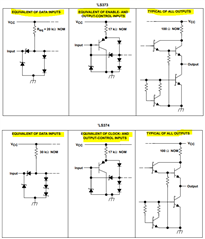
I placed the SN54SL373 and the SN54SL374 onto my PB-503 Proto Board. I connected the devices utilizing the specified resistors, reference page 5 of the datasheet. I connected VCC pin 20, GND pin10 , 1D pin3 to +5V. I measured 1Q and it was low. I then applied +5V to Ct pin 11, then dropped it. I then measured 1Q and it was still low. The +5 was not latched to 1Q.

Best Regards,

Ray Vincent

  • Hi Ray,

    Page 5 of the datasheet, (image above for reference) is showing the internal structure of the inputs and outputs fo the device -- it does not have any type of recommendation for external resistors.

    Can we get a schematic of exactly how this is connected? Is the Ct pin being forced low, then high just by using a wire? Or was it only forced high then left floating?

    What is being done with all the other pins during this time?  What load is connected to the outputs?  We would prefer 50pF (or 47pF, which is more readily available).

  • Hi Emrys,

    Good Day. I already send to your email the schematic design of our customer. Please help to check it on your email. Thank you very much for your support. I really appreciate a lot.

    Best Regards,

    Ray Vincent

  • I don't see any issues with the connections except that there is no bypass capacitor indicated for the SN74LS374 (the part # has a typo in the schematic, replacing LS with SL).

    Looking in the datasheet for the processor, I found that Port 0 is open-drain, so it will not be able to drive the outputs into the 'high' state by itself. It will need to have external pull-up resistors to drive the inputs to the SN74LS374 into the 'high' state.

    There is a mention of Port 0 being able to be switched into "External Bus Mode" and it will be able to drive high, but I didn't look further into how that might work. I'm not sure if that's just a software setting or if they are indicating what happens when an external resistor is used to drive the output 'high.'

    I'd recommend to just add pull-up resistors to all the Port 0 pins. To ensure that the SN74LS374 inputs can be driven into the high state, I would recommend starting with 100k pull-up resistors as it shouldn't take much to drive those high and the processor outputs don't appear to have a lot of drive strength.

    Have they considered switching to a more modern solution? They could control that seven-segment display with an SN74HCS595 and it would allow for fewer control pins (4) and would require much less power to drive.