This thread has been locked.

If you have a related question, please click the "Ask a related question" button in the top right corner. The newly created question will be automatically linked to this question.

Interfacing SN74LV123 Multivibrator to an MSP430

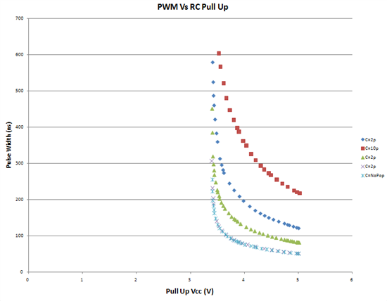
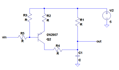
Do any techniques exist to programmatically control the pulse delay of the SN74LV123 monostable multivibrator using a microcontroller. Typically the an R and C create the normally fixed RC time constant to create a fixed pulse delay. Any ideas on how I can interface this control to an MSP430. Typical pulse delays are for my application is typically around 200ns @ 1-2 MHz.

  • It would help a lot if you'd describe the needed range and resolution. Given that the '123 is driven by an external RC, with a pullup resistor and a capacitor to ground, two options are to use multiple resistors to I/O pins which are toggled between high and high-impedance, or to use a DAC output to vary the pull-up voltage. The latter lets you extend the time delay to infinity by reducing the pull-up voltage below the '123's upper transition threshold. If you need more details on the '123, an internal schematic can be found in http://focus.ti.com/lit/an/sdla006a/sdla006a.pdf (Does this forum have a "preview" button? I'd like to see what tags are possible. Let's try: Designing With the SN54/74LS123.)
  • Of course, A perfect solution for my application would be  50 - 300 ns pulse delay range, matched to the 12bit resolution of the available DAC. Thanks for that internal schematic that is going to help a great deal.

  • Did some testing with a simple RC and varied the pull up voltage gets the following results. Working on the knee of the curve in this configuration, seems to put me just outside my range in the linear regions.

  • H'm... the curves look like they don't go low enough to satisfy your range requirement without being annoyingly sloped near the (device- and temperature-dependent) trip point. Given that you have some headroom between the supply voltage and the ~3.3V trip point, you could get more DAC range by using the DAC and a resistor to generate programmable current sink and a PNP current mirror (e.g. BCV62) to source a copy of that current into the timing capacitor in lieu of the pull-up resistor. It produces a frequency (1/delay) linearly proportional to DAC setting, but at least you have more range (it caps when the DAC voltage is supply - 0.7V) to work with. I wonder if I could do something clever using a transistor's exponential voltage/current curve to approximately invert the 1/t function? Probably too unstable. How self-calibrating is your application? Can it servo out temeprature drift?
  • The current mirror is an interesting idea. I was going here with the following, it has good range but still very steep pulse width versus dac voltage over the linear range, plus it causes the LV123 to develop frequency dependencies.

    As long as I have decent resolution, range and response time, the micro's feedback control algorithm should take care of any calibration or temperature drift.

  • D'oh! Shows you how much I've forgotten about discrete design; that's much better. I should remember the presentation of BJTs in AoE, which starts with the transistor current source before developing all the other amplifier types.

    The one question I have is what's R4 for? R3/R5 scale the input voltage to Vdiv = (5 × R5 + Vin × R3)/(R5+R3) = 5 − (5 − Vin) × R3/(R3+R5), then we have the Q2/R2 voltage controlled current source, which holds the bottom of R2 at Vdiv + Vbe, so Q2's emitter current is 5 − Vdiv − Vbe = (5 − Vin) × R3/(R3+R5) − Vbe, and its collector current is beta/(beta+1) times that.

    This is all (to first order) independent of the collector voltage, so what does R4 give you? I suppose at high current levels it reduces Vce, reducing Q2's beta, increasing the base current required to hold R2 at the desired level, which causes Vdiv to float up, reducing the current. This basically flattens the short-delay part of the curve. But you want to stretch the curve at low currents, i.e. the high-delay range.

    I'd add a decoupling cap to Q2's base (ideally, time constant chosen to match your feedback loop update rate) and lose R4.

    Or, maybe you're about to make me go Do'h! with an obvious explanation of why I'm smoking crack...