Hello, the following is the material test situation, please analyze the reason, thank you
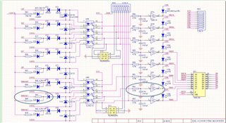
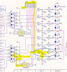
Test conditions: add 77-110v dc voltage signals to 110VG (x1-dbz26) of 110VCS (q-1) using the regulated power supply. Indicators 1a-4b on the panel are on. When the voltage is lower than 60V, indicators 1a-4b is off
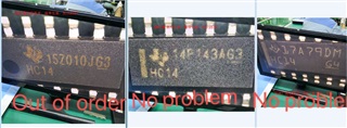
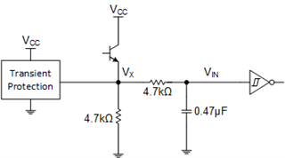
Abnormal situation: the 4A indicator light on the panel cannot be completely extinguished, and the voltage between the measuring chip and the ground is about 1V
1. Replace NXP brand materials and the fault disappears
2. Replace the samples provided by the original TI factory, and the fault disappears
3. Replace batch 2115 chips and the fault disappears
In addition: There is no problem that the two front screen prints are vertical lines. There is a small round pit in the front of the batch 2117+. Please see what is the difference