This thread has been locked.

If you have a related question, please click the "Ask a related question" button in the top right corner. The newly created question will be automatically linked to this question.

SN74LVC1G07:

Part Number: SN74LVC1G07

Hello,

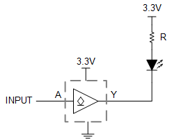
 I’m using a SN74LVC1G07 device to sink current from an LED. I have a 2-part question about this:

1) For a VCC of 3.3V, the data sheet has 2 sets of I_OL numbers: 16 mA and 24 mA. Which of those two numbers should I be looking at in determining the maximum current I can sink?

2) In normal operation the input of this buffer is high until a Fault occurs in which it will drive it low which is when I’d like the LED to come on. My question is that since this is an open-drain buffer and in normal operation the input is high (meaning the output will be in High Z state), would I need to pull-up the output so that the LED will not drive the High Z and come on when no Fault condition has occurred? I’m thinking that I need to use the pull- up but would like to make sure.

Thank you for your support

Ray

  • 1. The maximum current you can sink with a voltage drop of no more than 0.4 V is 16 mA. The maximum current you can sink with a voltage drop of no more than 0.55 V is 24 mA. The maximum current you can sink without damaging the device is 50 mA.

    2. An output in the Hi-Z state does not allow current to flow.

  • What constitutes a voltage drop of 0.4V vs a voltage drop of 0.55V? Once the input to the device is asserted Low, how would you know which of the two is your VOL?

  • Hi Ray,

    The output voltage is a direct result of the output current.

    Considering that you want to drive an LED, the question is, what current do you need to sink for your LED?

    Here's the circuit for driving an LED with the SN74LVC1G07:

    As an example, let's determine the required limiting resistor value for an LED with forward voltage of 2.2V at 20mA current.

    I'll first do this as an estimation, then I'll rework the same problem looking for a specific answer, and we can see the difference in the two.

    -

    Assuming our diode is on and there's 20mA being sunk into the SN74LVC1G07, then I can assume the output voltage is up to 0.55V as an estimation. This means that the voltage across our resistor, R, can quickly be calculated from KVL: 3.3V - 2.2V - 0.55V = V_R = 0.55V

    To get exactly 20mA from that resistor, we just use Ohm's Law to get the resistor value: R = V/I = 0.55/0.02 = 27.5 ohms

    -

    To get a better solution, instead of assume the worst case VOL of 0.55V, we can first determine the output resistance indicated by the VOL specification. In the datasheet, the supply is given as 3V, the output voltage is 0.55V, and the test current as 24mA, so the resistance is just the voltage drop across the output transistor (0.55V) divided by the output test current (24mA), or R = V/I = 22.9 ohms.

    * Just as a quick side note - this is a maximum resistance value because VOL is a maximum voltage value -- typically the resistance will be about half that, but let's use the max because that's a good design practice.

    Using 22.9 ohms and the known current of 20 mA, we now can get a better idea of the worst-case VOL, which will be VOL = I * R = 24mA * 22.9 ohms = 0.458 V.

    We can then use this new value the same way we did in the previous example to determine R. The voltage across R, V_R, is found with KVL as: V_R = 3.3 - 2.2 - 0.458 = 0.642 V, and that gives use the resistance directly from Ohm's law as R = V/I = 0.642 / 0.02  = 32.1 ohms.

    -

    Our two different approaches came up with pretty similar resistor values -- 27.5 and 32.1 ohms, respectively. Personally, I would just use a 33 ohm resistor and be done with it -- a 20mA LED looks pretty much the same when it's using 15mA or 25mA.

    Of course, I made a few big assumptions here -- you'd have to re-calculate using your own LED forward voltage and current.

  • Hi Emrys,

    Thanks for your thorough explanation. I had two follow up questions:

    1) You mentioned above that  

    In the datasheet, the supply is given as 3V, the output voltage is 2.4V, and the test current as 24mA

    where in datasheet states 2.4V as the output voltage?

    2)  I know that when you have more than one device on the bus, any device can drive the bus that is in a High Z state. I'm a bit baffled by the fact that Clemens said that an output in High Z does not allow the current to flow. Is there any more detailed explanation that by any chance?

    Thanks Emrys

  • Hey Ray,

    For (1), that's just a mistake. It should have been "0.55 V" and I'll update the post to reflect that to avoid future confusion for anyone who finds this post. You can see that my calculation was done with 0.55V.

    For (2), an open-drain device has 2 output states:

    1. Forcing the line low (sinking current to ground)

    2. High impedance, or Hi-Z mode, where it is neither sourcing nor sinking current.

    I'm not sure what you mean by a Hi-Z device driving a bus -- can you give a schematic of your bus? I might be able to clear this up by using an example, but I'd like to use one that's related to your system if possible.

  • Hi Emrys,

    The bidirectional buses have the Hi-Z state so that once they get off the bus after outputting data, they go into the Hi-Z state so that another device on the bus can drive the same signal.

    My schematic is pretty much like what you have shown with the buffer sinking the LED current. It happens that the input to the buffer is high in the normal state and it only goes low in case of a fault. Therefore, the LED should only come on when there is a fault condition. However, since the output of the buffer is in a Hi-Z state during the normal condition, then according to the definition below for Hi-Z, it can be driven by the LED. That’s why I was thinking that a pull-up on the output of the buffer will prevent the LED from turning on during the normal state.

    https://www.maximintegrated.com/en/glossary/definitions.mvp/term/Hi-Z/gpk/1175

    Unless you think that a pull-up on the output of the buffer will affect the function of this circuit, I can go ahead and add it just to have the footprints on the board. We can always depopulate it if it won’t be needed.

    Thanks

    Ray

  • Hey Ray,

    With the circuit I showed, the LED is off when the buffer is in the Hi-Z state (no current flows through the LED), but the output will be at ~3.3V (because no current flows through the LED, the voltage drop across it is 0V, same with the resistor).

    When the output is in the low state, the LED turns on because current sinks from 3.3V to ground through the LED and resistor.

    I don't see any reason why you would need to have a pull-up resistor on the output -- unless this line also goes to a digital input, in which case you'd probably want to add a 10k pull-up resistor.