This thread has been locked.

If you have a related question, please click the "Ask a related question" button in the top right corner. The newly created question will be automatically linked to this question.

CD74HCT4511: Datasheet inconsistency for font for digits 6 and 9

Part Number: CD74HCT4511
Other Parts Discussed in Thread: CD74HC390, CD74HC4067, CD4055B, CD4056B, CD74HC4543

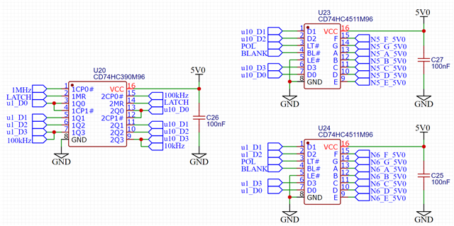
On the first page of the datasheet, the display figure below the pinout implies that segment 'a' is enabled when BCD = 6, and similarly segment 'd' when BCD = 9.

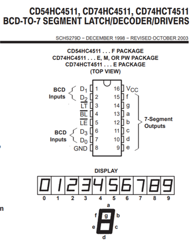
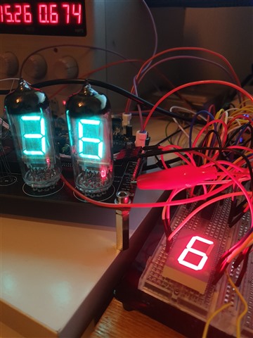
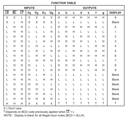
However, the function table contradicts this. Having tested the components I have with me, the function table is correct, and the overview on the first page is wrong.

Is there an equivalent part that does have these tails on digits 6 and 9, similar to the choice between LS47 and LS247 parts?

Thanks,

Phil

  • Hi Phil,

    Thanks for letting us know about the inconsistency here -- I'll make a note when I get back to the office on Monday that we need to update the datasheet.

    These types of drivers aren't really made anymore - usually an MCU + shift registers are used to create the same effect with much more flexibility in the outputs.

    This app note shows how this can be done in a very small footprint: https://www.ti.com/lit/ug/tiduc25/tiduc25.pdf 

  • Hi Emrys,

    Thanks for the prompt response! A bit of background regarding what I'm doing:

    I'm building an ISO8601 format atomic clock that goes down to microseconds. For >1s digits, I am using a shift register driven by a microcontroller that is also connected to a GPS module. This data is latched onto the outputs by a GPIO line that functions as the microcontrollers PPS output.

    However the <1s digits are directly clocked from the atomic frequency reference. The latch line for the shift register also serves as the reset to the CD74HC390 counters I am using. I'm then chaining several of these together to get all 6 <1s digits.

    Clocking 154 segments worth of data in each microsecond didn't seem feasible to me, so I went with a logic based approach instead. I'm also very aware that it's somewhat pointless having a clock that displays microseconds, but this is more for my own enjoyment than any sort of practical purpose Slight smile

  • Hey Phil,
    That's pretty interesting -- and your reason for doing it is the same reason I do most of my home projects. At best mine end up being moderately useful, but they're always fun to work on Slight smile

    If you really want the 'tail' to light up for the 6 and 9, you could add some external logic gates to turn it on 'manually.'

    One relatively easy method is to use a 16:1 mux like CD74HC4067. The channel select inputs would be the same as your inputs to the HC4511. You just have to hook up the mux in series with the LED that you want to control directly, then apply VCC to the input that corresponds with the appropriate digit.  The mux contains all the decoding circuitry, so it's a little less messy than adding a bunch of gates. 

  • The CD4055B/CD4056B have tails, but there is no HC version.

  • Thanks Clemens -- I had thought there was one, but I didn't find it when I went looking this weekend.

  • Thanks Clemens, I did look at the CD devices, but the propogation times seemed to high for my application.

    I did discover that the CD74HC4543 device appears to have tails, so I've managed to find a supply of them (not easy!) and will give them a go when they turn up this week hopefully! Slight smile

  • Hi all,

    Just to confirm, the CD74HC4543 device works as expected, complete with 'tails'. Just a shame they don't come in SOIC packages!

  • Hey Phil,

    Thanks for letting us know. Those nixie tubes look awesome -- I'll bet the whole project is going to come out looking really great.