This thread has been locked.

If you have a related question, please click the "Ask a related question" button in the top right corner. The newly created question will be automatically linked to this question.

LSF0204D: LSF0204DRUTR partial power down mode

Part Number: LSF0204D
Other Parts Discussed in Thread: TXS0102

Hi, Regarding Partial power down feature of LSF0204DRUTR datasheet shows,

PARAMETER                            TEST CONDITIONS                                                                 TYP

Ioff Power Off Leakage Current Vref_B = Vref_A = 0 V, VEN = GND IO = 0, VI = 5 V or GND  ±1 µA

9.3.5 Ioff, Partial Power Down Mode When Vref_A, Vref_B = 0, all of data pins and EN pin are Hi-Z.

Does this mean if ANY of Vref_A OR Vref_B are at 0V then IO's will be in Hi-Z? datasheet says "When Vref_A, Vref_B = 0, all of data pins and EN pin are Hi-Z."

Does this device has VCC isolation feature or just partial power down?

Thanks,

Reza

  • During normal operation, a small current flows into Vref_B and out of Vref_A. This requires only a voltage difference between Vref_A and Vref_B, so it happens also when Vref_A = 0 V. (In that case, a small current can flow between the Ax and Bx I/O pins when the input voltage is 0 V.)

  • Hi Clemens,

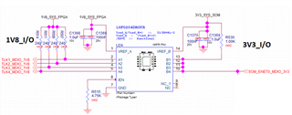
    Refer to the snapshot below,

    1V8 and 3V3 power rails will start at different times, one sooner than the other one and I want to make sure there won't be any back-drive from 1V8 side to 3V3 side or vice versa.

    Does LSF0204DRGYR partial power down mode can isolate the two domains or not?

    This chip per datasheet has partial power down mode feature not VCC isolation.

    Thanks,

    Reza

  • When the 3.3 V supply powers up first, a current can flow into the 1.8 V supply. (This current is limited by the internal 200 kΩ resistor.)

  • Hey Reza,

    This device does not have the VCC Isolation feature that allows one of the supplies to be powered and still keep the I/O disabled. For this device, both VrefA and VrefB have to be 0 V for the Ioff circuitry to be active.

    It looks like you are working with O.D. MDIO signals, it may be better for you to use two TXS0102 devices for this since it does have VCC Isolation and as long as one of the supplies is at 0 V, the I/O are disabled.