This thread has been locked.
If you have a related question, please click the "Ask a related question" button in the top right corner. The newly created question will be automatically linked to this question.
Hi,
I'm using CD74HC4515 in our controller PCB and I need a clarification regarding status of the Latch Enable (LE) pin. Actually it's somewhat confusing for me since the data sheet is common for both CD74HC4515 and CD74HC4514. So kindly give a brief description on the LE pin of CD74HC4515.
Thanks and Regards,
Arya G Lal
The only difference between the 4514 and the 4515 is the polarity of the outputs.
On the 4514, the selected output is high, and all other outputs are low.
On the 4515, the selected output is low, and all other outputs are high.
For both devices, when /LE is high, the state of the outputs is determined by the current state of the four Ax pins. When /LE is low, the outputs do not change.
Thank you for the swift response.
We are using F28379D MCU, interfacing four external ADCs and CD74HC4515 is used for the selection.
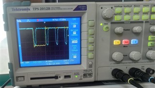
We put the /LE permanently high, and the EM1OE of F28379D is given to the Enable pin (/E) of 4515. The waveform we've got is attached herewith,
where the blue coloured one is the EM1OE and the yellow coloured one is A0. At the same time, there's a low at A1.
I'm really sorry that my query was incomplete. Actually, when I apply the logic for selecting the Y0 using Ax pins as per the decoder truth table, Y1 is also getting selected (both Y0 and Y1 are getting selected). I don't know whether there is any issue with Enable (/E) input. So please clarify.
When /E is low, exactly one output is low. When /E is high, all outputs are high.
Please specify the state of all input and output pins.