This thread has been locked.

If you have a related question, please click the "Ask a related question" button in the top right corner. The newly created question will be automatically linked to this question.

SN74LVC16T245: Interference in ground isolate

Part Number: SN74LVC16T245
Other Parts Discussed in Thread: DRV135, , LSF0108, SN65HVD82, SN74CBTD3384

Hi Everyone,

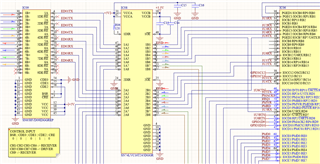
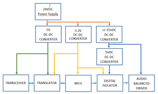
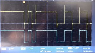
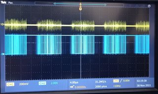
I use SN74LVC16T245DGGR to translate voltage level between MCU (3.3V) and RS485 transceiver (5V). Aditional, MCU generates audio tone then it is convert to balance audio by means the DRV135UA. DRV135UA use an isolated power supply +/-15VDC.
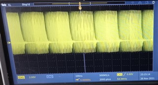
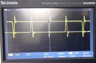
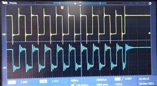
I have a hum at the DRV135UA output pins. I checked each ICs and found that SN74LVC16T245DGGR generate noise when is placed in PCB.
SN74LVC16T245DGGR have bypass capacitors on power supplies but I don´t know why produce noise on isolated power supply.


Could someone help me?

  • Hello Samuel, 

    I am familiar with the SN74LVC16T245DGGR, so I may be able to help, however, I am not sure I fully understand the setup. 

    Are you going from MCU --> Translator --> RS485 Transceiver --> DRV135?

    If so, it seems like the signals are all in the right range. 

    Note that the SN74LVC16T245 does not isolate the gnds between input and output, so there could be noise coupling. 

    The only thing that comes to mind from the SN74LVC16T245 that might be causing some issues is the fact that it has very strong output drivers, so if it is driving the SN65HVD part directly with very light loads, then there may be a bit of ringing/reflections on that line. Do you have a scope shot of the output of the LVC16T245 device?

    If you notice ringing on the line then you can add output series damping resistors (resistors in series with the output) to help reduce the overshoots and undershoots at the output.

    Hope that helps.

    Best,
    Michael

  • Hi Michael,

    Thank you for your reply., In order to clarify my design, see below block diagram:

    MCU receives control command from several remote stations via RS485 channels to generate tone for every command type, 3.3v and 5V are power supplies and those share the same ground reference and +/-15V and 5V are isolated power supplies with another ground reference.

    In idle conditions and no commands sent, the output at audio-balanced driver pins have a low noise of 20mV. We desoldered IC´s one by one  and found that SN74LVC16T245DGGR generate noise at output balanced audio driver. When removed SN74LVC16T245DGGR, noise was extinguished.

    I don´t know What´s wrong.

    Please, any advice.

    Best Regards,

    SAM

  • Hello Sam,

    Ok, so the presence of the SN74LVC16T245 is causing noise in the system, but its not because its driving the audio signal, it is doing something else in the system.

    As mentioned previously, the most likely cause is that the LVC16T deviceis driving the SN65HVD part directly with very light loads. There may be a bit of ringing/reflections on that line that are causing system noise. Do you have a scope shot of the output of the LVC16T245 device to check this?

    If you notice ringing on the line then you can add output series damping resistors (resistors in series with the output) to help reduce the overshoots and undershoots at the output.

    Best,
    Michael

  • Hi Michael,

    In datasheet of SN74LVC16T245, on page 7, output current is -32mA and 32 mA, SN74LVC16T245 and SN65HVD09IDGGREP are interconnected directly, Is there problem? 

    Best Regards,

    SAM

  • Sam,

    The problem does not have to do with whether or not the SN74LVC16T245 is capable of driving the inputs of the SN65HVD device. It has to do with the fact that the output drivers are very strong for driving the high-impedance inputs of the SN65HVD device. 

    Essentially, its a low impedance driver (say 10Ohms give or take) turning on and driving into a high Z load. There is a significant impedance mismatch between the load and the driver which has a tendency of causing reflections or overshoot. 

    There is an FAQ which goes into this in detail here: https://e2e.ti.com/support/logic-group/logic/f/logic-forum/763609/faq-what-happens-when-i-connect-a-logic-device-s-output-to-a-50-ohm-transmission-line 

    Check the section about "What can I do to keep transmission lines from affecting my logic signals?"

    I can't say 100% for sure that this is what is causing the problem, as I don't have enough information, but it seems to be the most likely culprit at this point in time.

    If you could share a scope shot of the output of the LVC16T switching, then it would help to confirm. And if you are seeing a lot of line reflection and overshoot on the line, the best way to reduce this is to put a resistor in series with the output of the LVC16T.

    Best,
    Michael

  • Hi Michael,

    You are right, the problem is due to ringing/reflections, attach scope capture:

    I never considered to match impedances, but I want to know what is value or range and type of resistors that I should connect. Is there any compatible voltage translator with SN65HVD device ?

    Thanks a lot.

    Best Regards,

    SAM

  • Sam,

    You can't match impedance exactly in this scenario because the device isn't a line driver and if you match exactly then you will get 1/2*VCC at the input of the SN65HVD device.

    For the voltages you are using the device you have is the best option.

    For series limiting resistor, a good start is probably in the 25-100Ohm range. Maybe start at about 100 ohms and see if that cleans up the signal and helps eliminate the noise. The location of the resistor should be in series with the output driver. Essentially connect 100 ohms from the output of the device to the input of the SN65HVD device.

    Best,
    Michael

  • Hi Michael,

    Proposed solution doesn´t solve it , I start with 120 ohm and decrease the value by resistors in parallel at 60 ohm and them at 40 ohm but  only reduce peaks and oscillation is still present  as shown below

     SN74LVC16T245 Output before place resistor  in serie between SN74LVC and SN65HVD without generated signal by MCU

    Comparative signals  before (yellow) and after (blue) leads resistor at 60ohm

    Comparative signals  before (yellow) and after (blue) leads resistor at 40ohm

    When output sn74 and isolated ground were measured with its own reference, respectively, I noted that both waves have a similar sequence as shown below

    I will implement a new solution with Shottky diodes to translate voltage level.

    Best Regards,

    SAM

  • Hi SAM,

    You might consider using a passive voltage translator like the LSF0108. The device doesn't include any drivers like the LVC family translators, so you won't have issues with overshoot.

  • Hi Emrys,

    I implemented a solution with a B340A-E3/61T diode in serie and 44.2kohm pull-up resistor were on hand and these were connected between MCU and SN65HVD09DGGR in order to remove SN74LVC16T245. For more detail connection, please see image below where it was extracted from SN65HVD82 datasheet.

    I´m testing with 3 communication channel USART at 38400,None,8,1, I have excelent result, no more noise or overshoot Only have a problem with MCU about Framming Error when interchanging input signal between ports, That could be because of SN65HVD09DGGR doesn't has fail-safe input.

    I want to know if can use SN74CBTD3384 according to the report SCDA003B by Nalin Yogasundram

    Best Regards,

    SAM

  • Hi SAM,

    Thanks for letting me know about the new solution.

    Those aren't parts my team supports -- please create a new thread using one of the part numbers and the correct team will be automatically notified. I would recommend to link to this thread in the new thread, and mark this one as resolved.