Hi,
I have any questions.
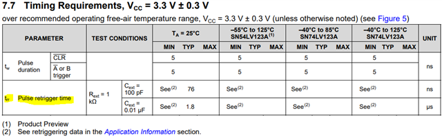
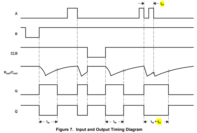
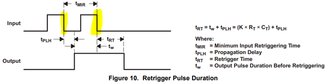
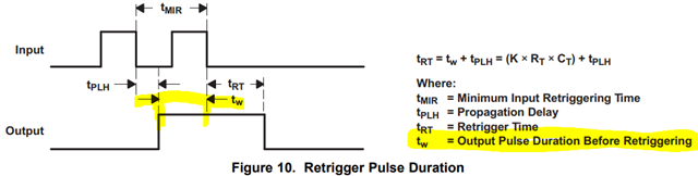
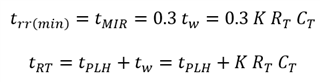
1. Which of tMIR (= 0.3 x tw), tMIR (tPLH + tw) and trr is the minimum retrigger time?
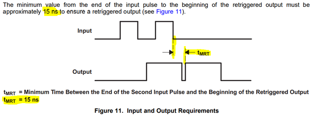
2. The data sheet "10.2.1.3 Retriggering Data" states "the two adjacent input signals must be tMIR apart, where tMIR = 0.30 x tw.".
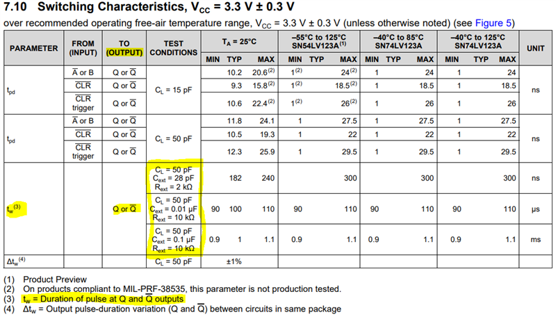
Which of "7.7 Timing Requirements, VCC = 3.3 V ± 0.3 V" and "7.10 Switching Characteristics, VCC = 3.3 V ± 0.3 V" is this tw?
Best Regards,
Nishie