This thread has been locked.

If you have a related question, please click the "Ask a related question" button in the top right corner. The newly created question will be automatically linked to this question.

TXB0104: Bouncing effect

Part Number: TXB0104
Other Parts Discussed in Thread: TXU0304, SN74AXC4T774,

Hi Team,

Good day! Posting this in behalf of the customer. Here it is. 

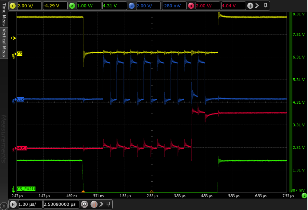
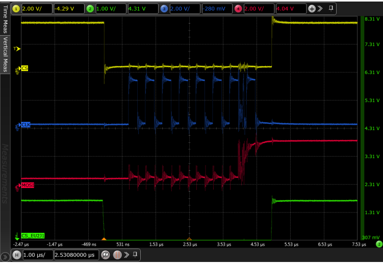
We are working on TXB0104RGYR in one of our design
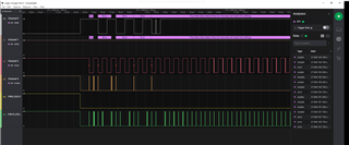
we found some bouncing effect on output pin 10.
I mean, signal is not consistence w.r.t input signal.
if the device is in idle, its output is fine and same as input, incase if we try to probe the signal/connected to another device the output is bouncing.

Best regards,

Jonathan

  • Hey Jonathan,

    We will need scope shots of the issue instead of logic analyzer captures. It would be good to see the input and output signal that is having problems. 

  • Dylan,

    here attached some signal captures 

    Without connecting any device

    Without slave (scope connected at LIN HEADER) With Aardwark slave connected at LIN HEADER:

    with connecting to aardwerk tool

  • Hi Narendar,

    I would've liked to see the input and output of the problem signal, but from the scope captures I can see what could cause issues. With nothing connected there is a lot of ringing and crosstalk, this indicates to me this is likely caused by a non ideal layout. I assume connecting the aardwerk tool adds in more line length through a cable as the signal integrity gets worse. The best way to fix this is to clean up the layout providing nice clean current return paths. It may also help to have some source termination to help dampen the ringing, adding ~33 ohm series resistors close to the output would likely do the job here.

  • Hi Dylan,

    thanks for the response, we have a good and simulated layout on our board, also i don't think this noise can effect on low speed signals, anyway we will re capture the level translator signals and let me provide you , thanks 

  • Hi Dylan,

    thanks for the response, we have a good and simulated layout on our board, also i don't think this noise can effect on low speed signals, anyway we will re capture the level translator signals and let me provide you , thanks 

  • TXB signals always are high speed; what matters is not the signal frequency but the rise/fall time of the signal edges.

    The TXB signals go through a connector and cable. This is a likely cause of such problems.

    Are any of the signals actually bidirectional? If not, consider a buffered translator like the TXU0304.

  • We are using  TXB0104RGYR for level conversion of 1.8V to 3.3V. The intended interface is SPI.


    Do you mean that TXB0104RGYR cannot support bidirectional?


    The cables are at acceptable length limit. When we connect Aadvark analyzer directly, we are seeing bounce effect as informed earlier.


    Hope the layout reference from level translator to the Header is shown previously.


    Could you provide your suggestions for this issue?


    The circuit reference is shown below,

  • The TXB does support bidirectional signals. But this support requires a special I/O driver architecture that imposed quite restrictive limits on the I/O signals; see sections 8.3.3 and 8.3.5 of the datasheet.

    It appears that your board (or the board when connected to the analyzer) violates these limits, so the TXB cannot be used.

    Your SPI signals are unidirectional, so you can simply use a buffered translator like the TXU0304 or SN74AXC4T774.

  • Hi Clemens Ladisch,

    Thanks for the reply,

    we have analyzed our board based on below points,

    1. Bus capacitance : "only one device" connected, one to one connection on the board from IC header to Aardvark tool


    2. Total length from TXB to header is 17mm max, attached total etch length for your reference.

    3. We have good GND reference  at layer 11(GND Plane), and signals are routed on layer 12(Blue), attached layout image below

    Please review and let us know.

    if you still feel we need to change the part, please suggest pin-pin compatible P/N, otherwise it will greatly impact on our design and schedule.

    Thank you

  • Apparently, the total capacitance of the traces, the connector, the cable, whatever is connected at the other end of the cable, and the analyzer is too large.

    The TXU0x04 is pin compatible with the TXB0104, but does not exist in the RGY package.

  • Hi Clemens,

    We have changed the existing IC TXB0104RGYR to  TXU0304Q1PWR, and attached the schematics for your review, kindly check and provide your confirmation, 

    Thanks for the support     TI_TXU0304Q1PWR_Sch_review.pdf

  • With the TXU0304, the first three channels go from A to B, and the fourth, from B to A. So you have to move the MISO signal to the B4/A4Y pins. (A/B indicates the voltage; the Y pins are outputs.)

    The second translator has two signals that go from 3.3 V to 1.8 V. The only way to handle this with the TXU0304 is to have VCCA = 3.3 V and VCCB = 1.8 V and to move the CS1_N signal to the B4/A4Y pins.

    Everything else looks OK.