This thread has been locked.

If you have a related question, please click the "Ask a related question" button in the top right corner. The newly created question will be automatically linked to this question.

SN74HC165: technology discussion

Part Number: SN74HC165
Other Parts Discussed in Thread: CD74HC165, , SN74HCS165, ISO7740

Dear, 

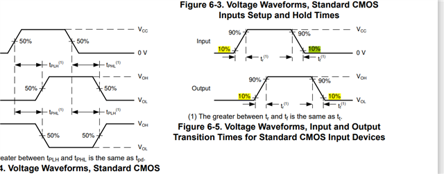
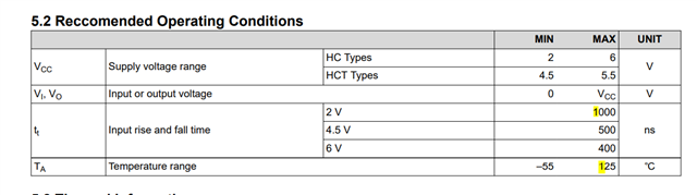
the datasheet Note 2: When Vcc = 2V, Tt =1000nS =1000nS /V x (1.5V-0.5V)  ?  If Vcc=4.5V, Tt= 500nS/V x (3.15-1.35)=900ns, the chip will not be damaged. As long as it is below 1.35V or above 3.15V, it is safe?

If not, please help to explain, thank you very much ~

Is there a reference value for Vcc=5V?

  • Hi Cooper,

    There are several errors in the transition time specification that we are working on fixing.

    This specification is not actually a rate, but it is a total rise/fall time. Somewhere along the way of datasheet format updates, the units and name were changed to incorrect values.

    Δt/Δv should be tt

    ns/V should be ns

    These fixes are being made to most HC family logic datasheets.

    -

    Transition time is measured from 10% to 90%.

    Regarding the input transition time, faster is better. We would recommend to have the inputs as fast as possible, but never slower than the listed maximum times in the datasheet.

    You may find this video helpful for some clarification: CMOS logic standard inputs

  • Dear ,

    1.you said ''Transition time is measured from 10% to 90%.' , i am confused, the datasheet is referred to the threshold from VIL max to VIH min , for example, Vcc-4.5V, but 10%~90%  is 0.45V~4.05V, however , VIL max to VIH MIN is 1.35V~3.15V as datasheet,  so Which one should I take as the standard ?

    2. CD74HC165 datasheet is referred to 10% ~90% 

  • Hi Cooper,

    1.you said ''Transition time is measured from 10% to 90%.' , i am confused, the datasheet is referred to the threshold from VIL max to VIH min , for example, Vcc-4.5V, but 10%~90%  is 0.45V~4.05V, however , VIL max to VIH MIN is 1.35V~3.15V as datasheet,  so Which one should I take as the standard ?

    Everything that I've said and the datasheet says are in agreement here.

    I don't see anywhere in the datasheet where it claims the transition time was measured from VIL to VIH. It does state that you should not have the input between VIL and VIH for an extended time, which is correct.

    It also clearly defines the measurements for rise and fall time, which can also be referred to as transition time, as 10% to 90% in the PMI section:

  • Dear ,

    I don't see anywhere in the datasheet where it claims the transition time was measured from VIL to VIH. It does state that you should not have the input between VIL and VIH for an extended time, which is correct.

    “an extended time”  , Could you give me  the exact time ?

  • 1、The transition time (tr) is clearly defied, and clearly required in the cd74hc165.  

    The confusion is the transition time  (tt) requirements for sn74hc165,  whether it can be measured from VIL to VIH?  Is it different from definition of (tr) time measured from 10%-90%?

    2、 Why the  transition time requirements are  different between cd74hc165 and sn74hc165?  Is the  transition time  (tt) requirement measured from VIL to VIH  suitable for CD74hc165? Infact, there are not any mistake while the tt time can be satified but the  tr  time can not be satisfied.

  • 1、The transition time (tr) is clearly defied, and clearly required in the cd74hc165.  

    The confusion is the transition time  (tt) requirements for sn74hc165,  whether it can be measured from VIL to VIH?  Is it different from definition of (tr) time measured from 10%-90%?

    No, the input transition time is measured from 10% to 90%, which I have already addressed in this thread. You can determine the transition rate based on the voltage and time -- for example, at 4.5-V supply, 10% to 90% transition time is 500ns max, therefore the transition rate is  138.9 ns/V (500ns / 3.6V).

    VIL is larger than VCC * 10%, and VIH is less than VCC * 90%, so the time between those will be less to maintain the same transition rate. For example,  For VIL of 1.35V and VIH of 3.15V, the total time in that region is (3.15 - 1.35) * 138.9ns/V =  250ns.

    2、 Why the  transition time requirements are  different between cd74hc165 and sn74hc165?  Is the  transition time  (tt) requirement measured from VIL to VIH  suitable for CD74hc165? Infact, there are not any mistake while the tt time can be satified but the  tr  time can not be satisfied.

    CD74 parts were developed and specified originally by Harris Semiconductor and acquired by Texas Instruments, while SN74 parts were created by TI.

    The same functionality applies to all logic devices.

    -

    Exactly what are you trying to do with this device? Do you need help with a system design to prevent slow input transitions? Personally, I would recommend switching to the SN74HCS165, which has no limitation on the input transition rate because of Schmitt-trigger input architecture.

  • Dear Emrys Maler

    Thank you very much,actually,we already switched to 74hcs165, however, there are some problems during the application of 74HCS165.

    Our apllication is shown as below

    Almost 50 74hc165 chips are applied in 16 logic card of one chassise sharing the same control sigals (CLK /LD )  from the CPU based card throu gh the backplane.

    However, there always some bits are not correctly transmited to CPU card when using the 74hcs165, we alreay checked that the inputs are stable logic , and the tr time for clk is about 400ns-1us with different configration.  When we replaced the  74hcs165 with cd74hc165, the transmition is very good without any mistakes, but the tr/tt time can not meet the requiremens of cd74hc165.  The mistakes will be worse during the Radiate Susceptibility test aroud the 100M frequcey for 74hcs165. That's why we very care about the tr/tt time.

    Q1: Are there any problem in our application scheme? 

    Q2: We believe that the 74hcs165 has better performance for the slow tt/tr time, but why there is no transmition mistakes in 74hc165 even the tr/tt time are not meeting the requirements of datasheet?

    Looking forward you reply!

    Many Thanks!

                                                                                                                                           Chen Yinjie

  • I expect that connecting 50 devices directly to your processor will overload it. Most modern processors are designed to handle relatively light loads (20pF), and each device adds 5pF -- plus the trace capacitance to the device. Additionally, I expect that the distance between registers is relatively large based on your description. This can cause mismatches in clock and data timing that can result in lost data. It sounds like you're getting lucky with the CD74HC165 working and it may not work under all circumstances (across temp / process corners)

    This graphic shows how data can be lost if the clock arrives in the wrong order:

    -

    In order to ensure that no data is lost due to timing, the clock should always arrive at the last device in the chain first and propagate towards the first device. The following graphic shows the appropriate method to avoid data loss:

  • Dear Emrys Maler

    In our  scheme,   I don't think we have this problem you mentioned.

     1) 50 devices are not directly to the processor, firstly  they are driven by the  transistor,  as the tr/tt issues, and we have replace the transistor by iso 7740 two days ago, and the tr/tt time is meet the requrements of 500ns, but there there are still  some mistakes for 74hcs165.

      2)  3-5 chips 7hcs165 are designed  in each 16 logic card, and each logic card is controled by processer  in sequence. It means only 3-5 chips 74hcs165 are cascaded and controled by the processer.

      3) 3-5 chips in one logic card is arranged together in PCB borard, we believe there are not large delay between the 74hcs165 in the same logic card.

      Now our modifed scheme is:

      1) 74hcs165 is replaced by 74hc165

      2) The driven circuirt is re-designed, using iso7740 to solve the tr/tt time


    Looking forward you reply!

    Many Thanks!

                                                                                                                                           Chen Yinjie


  • The only real difference between the HC and HCS parts will be the input thresholds -- HCS has Schmitt-trigger inputs while HC has standard CMOS inputs. One has separate positive and negative thresholds, while the other has a single value for both.

    Slow edges can cause errors with HC parts, but not with HCS parts. It is possible that the same input that could trigger an HC part would not trigger HCS, however, as HCS has an increased threshold -- for example, with a 5V supply, 2.6V could trigger an HC part, while it may not trigger an HCS part.

    I would recommend to carefully look at the waveforms and timing where you are having issues.