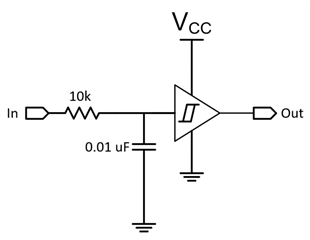
Do you know what does the symbol below stand for?
This thread has been locked.
If you have a related question, please click the "Ask a related question" button in the top right corner. The newly created question will be automatically linked to this question.
Do you know what does the symbol below stand for?
Hello
Does Ti have some delay trigger. I would like to make a delay circuit, maybe 200us to 1ms
Thanks!
Hi,
This circuit should get you close to 200 us delay (Calculated using 2.2RC), you can increase the resistor value to get more delay as needed.
I would recommend using the SN74LVC1G14 as the Schmitt Trigger buffer.
Regards,
Sebastian
Hello
SN74LVC2G74 has a CLK pin. What kind of signal should be inject in this port?
Thanks!
The SN74LVC2G74 acts on any positive edge at its CLK input.
I do not know what you want to achieve with this device.
SN74LVC2G74 has a CLK pin. What kind of signal should be inject in this port?
The CLK input should be a fast transitioning (digital) signal that is less than VIL in the LOW state and greater than VIH in the HIGH state.
Hello Emrys
Thanks for the support. And for the CLK frequency, is there some consideration?
Yes - the datasheet has specifications for input signal timing in tables 6.6 and 6.7.
Hello Emrys
Yes, it specify the max CLK frequency. Then how to consider the min CLK frequency
And how to get the clock source? I wonder the general method to get the clk generator. Is it from the Micro output or there is some dedicated CLK source?
There is no minimum frequency, i.e., there is no maximum time between clock edges.
That pin is called "clock", but you are not required to provide a regular square wave. You send a positive edge whenever you want to latch the value at the D input to the outputs.
Hello
Does that mean the CLK pin just need a positive edge. And I just need to give the edge before the signal, then the status could be latched. Sorry for the stupid question, I do not have much experience in logic.
Or can I say the edge must be given before the signal disappear. The time slot between 2 positive edges must be short than the signal duration.
Thanks!
The setup time (tsu) and hold time (th) specifiy how long before and after the positive edge the voltage at the D input must be stable.