This thread has been locked.

If you have a related question, please click the "Ask a related question" button in the top right corner. The newly created question will be automatically linked to this question.

bidirectional buffer with autodirection

Other Parts Discussed in Thread: SN74LXC8T245, SN74LXC2T45, SN74LXC1T45, SN74LVC16T245, SN74LV125A, SN74LV4051A, TMUX1208, SN74LVC1G125, TXB0104, SN74LV125, TXB0108

Hi,

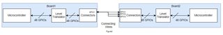
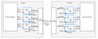
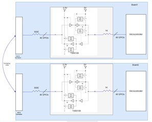
We are looking for bidirectional buffer/level translator for one of our application. We have 48 gpios which can act as both input and output(configurable in SW). We want to increase drive strength(upto 5mA) of microcontroller by adding buffer . Microcontroller operates at 5V level and hence we are looking for  bi-directional buffer with 5V translation in either direction as any gpio can act as input or output. We have gone through multiple level translators chips which states for translation at VCCA(low side)<=VCCB(high side) for upto 5.5V but they also mention for proper operation, VCCA should be lesser than VCCB. So we are little confused if chip can be used by supplying 5V on either end or not. Can anyone please suggest any chip which can serve our purpose.

Regards

Narendra Singh

  • An auto-bidirectional translator cannot act as a buffer, because it does not actually know what direction is desired. (TXS/LSF translators are passive switches. On TXB translators, the output drivers on both sides are always active, but weak.)

    The only way to increase drive strength is with a direction-controlled translator like the SN74LXC1T45/SN74LXC2T45/SN74LXC8T245/SN74LVC16T245.

  • Hi Clemens,

    I have attached architecture of our system. We have 2 identical boards. We need 48GPIOS to act as input or output(configurable in SW at run time through some interface). Gpios are terminated in connector as mentioned. The 2 boards are connected through external wires (basically we want to test continuity of cable).   We configure random gpio as output and set to high in board1 and which is read in board2 by configuring the pin as input. For some cases(as shown in figure2, to check continuity,assume gpio1 is configured as output high which is sensed at multiple gpios on board2(cable may have internal short and hence we need to check if all the gpios on board2(gpio1,gpio2,gpio3 etc) connected to gpios1 on board1 through cables read high logic or not. In doing this, when we have to sense multiple gpios on board2, voltage drops and we are not able to read correct state of continuity. Number of shorts in cable is undefined which need to be sensed correctly on board2. 

    To reduce this drop only we wanted to add level translators in between to increase the drive strength. As i said, any gpio need to act as input or output and hence we need bidrectional control.I just wanted to know if level translator can serve our purpose(currently we do not have level translator in our design and we want to add if it solves our problem).

    Regards

    Narendra Singh


  • Hi Narendra.

    Please note that the bidirectional devices are not designed for high drive strength, and would not be able to support the intended 5mA application.

    Hence, the recommended direction controlled devices per your GPIO configuration should be able to control the intended direction, thanks.

    Best Regards,

    Michael.

  • You do not actually need a different voltage, so you can use plain buffers (e.g., SN74LV125A). But you require additional GPIOs from the microcontroller (one per possible output).

    Alternatively, for fewer additional GPIOs, use a single strong buffer (e.g., SN74LVC1G125) and route it to one of the outputs with passive switches (e.g., SN74LV4051A, TMUX1208).

  • Hi Clemens,

    As mentioned, our signal is bi-directional in nature. we need to have common board which can configure gpios connected to connector as input or output as shown above in block diagram. any number of gpio on either board1 or board2 can act as input or output which needs to be sensed for continuity on the other board. number of input or output ports on either board is not defined as it varies from one requirement to the other. the board under design is to be designed as common for sensing continuity and can have N number of shorts or may not have short in boards connecting wires at all. Beside this, there can be multiple boards connected together to some parallel interface bus-not shown in block diagram and any number of gpios need to act as input/output which is configurable in SW.

    Due to this reason, uni-directional buffers do not suit our application as for one continuity check, gpio on board1 can act as input while for the other continuity check requirement, it may act as output and it is true for all the 48gpios and for any numbers of boards.

    I am bit puzzled if such solution is possible.

  • Then use buffers (74xx125). You can enable them if you need outputs, and disable them for inputs (you can use the MCU inputs directly).

  • Hi Clemens,

    Just wanted to know if you meant to use circuit like this? When to be configured as output, set corresponding OE(enable pin) low and when required to

    configure as input, set corresponding OE pin high to sense in microcontroller directly?

  • Hi Michael,

    Just for academic interest, i wanted to know reason why bidirectional devices can't drive high current. I was going over specification of TXB0104 where they mention absolute maximum continuous output current as 50mA.

    So if this chip has 4 output, can't it drive even 10-20mA in total from 4 ports?

    Going over functional block diagram of TXB0104, is this limitation because of 4K internal resistor connected in series to ports?

    If yes then may i know what does this 50mA absolute maximum output current correspond to?

  • Yes, this circuit increases the output drive strength.

    That 50 mA value in the TXB datasheet is an absolute maximum rating, i.e., your circuit must not try to draw more current out of the pin. But this value cannot be achievd in practice. The rated drive strength is in the test conditions for VOL/VOH.

  • Hi Clemens,

    SN74LV125 circuit proposed above is quite complicated as we would need additional gpio for enabling of each ports. Another big flaw in that architecture was we can't short port directly for sensing in micro-controller as after shorting, adding buffer doesn't make sense at all as short is low impedance path. Instead of that for sensing input, if we could control shorting directly by switch then it might work which will need another gpio to control and circuit will get quite complicated.

    we are proceeding with bidirectional level translator TXB0108. As per internal block diagram, output signal is push-pull type which should be able to drive at least 2-3mA current on each port. i was wrong in my previous post that current is limited by 4K internal resistance which is not the case as output is push-pull type. we have added series resistance in each port to limit the current and avoid any mis-configuration in gpios. I do understand we should not consider for drawing 50mA. In actual we will draw very less current. only issue we have is, i couldn't find level translator with auto-direction with VCC as 5V on either side. Hence i am going to use 3.3V.

  • The one-shot circuit is active only for a few nanoseconds at a rising or falling edge. The DC drive strength is determined by the actual output driver, which sits behind the 4 kΩ resistor.

  • Hi Clemens,

    Thanks for your suggestions. We found root cause of drop when multiple pins were shorted. Actually pull down was enabled internally for pins configured as input which was draining around 100uA current at each port. When number of input short was increasing, drop was getting higher. We disabled it and added external 1Mohm pull down which solved the drop problem. Hence we didn't need to add any external circuit.

    Regards

    Narendra Singh