This thread has been locked.

If you have a related question, please click the "Ask a related question" button in the top right corner. The newly created question will be automatically linked to this question.

CD4050B: Amplifiers forum

Part Number: CD4050B
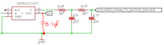
Other Parts Discussed in Thread: SN74LVC1G17

Hello,

I am searching for a TI 1 channel ic that do exactly the same as CD4050BDR (Non invert buffer but 1 ch instead of 6 channels), preferable in SOT package.

Can anyone please aadvice?

Thank you in advance

  • Hello,

    We do not have a signal channel version of the CD4050B, however we do have many single channel logic buffers.

    Can you tell me more about the specific application? What exactly are you trying to achieve with this single channel buffer?

  • Hi,

    the purpose is to pass an isolated  pwm control signal from a mcu to a driver ic on the other side, attched below is the schematic:

    Thanks

  • There are several 5 V single-channel buffers. Because of the slow output of the optocoupler, a Schmitt-trigger input might be a good idea, so use the SN74LVC1G17.

  • Hi Emrys,

    Thank you for your reply,

    Can you please take a look and advice if the schematic bellow is correct? and if all the resistors and capacitors/Values as noted also needed(R15,R16,R17, C9, C10)? 

  • Hello,

    I can't be certain of this circuit:

    This is not a TI part, and it looks like they have configured it as a common collector amplifier. Just looking in the Vishay 4N25 datasheet, it seems that the more standard configuration is common emitter, like this:

    What they have may work -- I'm afraid I don't know and they would need to do the circuit analysis or contact the manufacturer of their opto-isolator to get more information.

    My recommendation would be to design the circuit the way the manufacturer recommends, and if an inversion is required, that can be done at the LED inputs.

    If the PWM input is connected to pin 2, and pin 1 is tied to the positive supply (not sure what the voltage range of PWM is), then this would reverse the polarity of the signal and invert the output, without having to use the common-collector circuit that has limited voltage range.

    -

    For the SN74LVC1G17 operating at 5 V, I would recommend that a "HIGH" input be larger than 3.33 V, and a "LOW" input be smaller than 1.51 V to ensure the input is recognized correctly.

    The SN74LVC1G17 should have a 0.1uF bypass capacitor connected from the supply to ground placed close to the device.

    The output loading is no problem - with a 6kohm series resistor the output current is limited to less than 1 mA, which is far below the limitations of the device.

  • Hi Emrys,

    Thank you for your reply,

    Regarding the PWM values - they are between 0v to 5v max, and the opto 4n25 can be change with equivalent TI's if there are any? its noted just to use any opto that will make the isolation purpose, i am sure there is a better design than this (basicaly the circuit target is to pass an isolated pwm from the mcu side to the motor driver ic side with min components due to place issue).

    Appreciate if you can advice for a relevant 1 channel TI opto instead of the 4n25 so it will work smoothly with the SN74LVC1G17 for this purpose?


  • I do not support isolation, but I believe TI doesn't do optical isolation at all. You could open a new thread and request assistance from the isolation team.

  • Well noted, Thank you!