Hi Experts,
Seeking your assistance on this query:
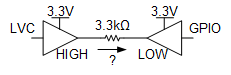
We are using SN74LVC1G17-Q1 Schmitt trigger and We tie the VCC to 3V3 and output 'Y' is going to IMXRT 117xx GPIO Pin.
We are limiting the 'Y' Output current through 3K3 Resistor as IMXRT 117xx GPIO Pin can sink upto 25mA and SN74LVC1G17-Q1 also Source upto 24mA for 3V3 Supply.
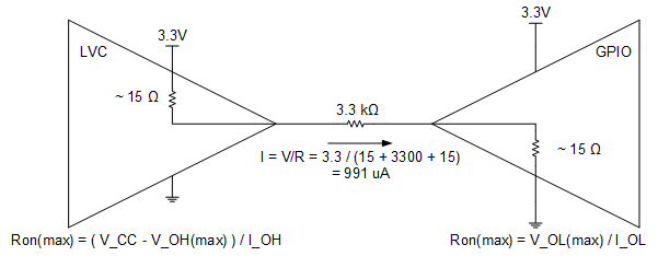
So want to know the device current in above case ? As per our understanding IO = 1mA (Y Current - sinking into IMXRT GPIO Pin) + 10uA(Icc) + 20uA(A input Current) = 1.03 mA ; is this understanding is clear.
As there is internal circuitry given in the datasheet, if that is available then please share.
Thank you.
Regards
Archie A.