This thread has been locked.

If you have a related question, please click the "Ask a related question" button in the top right corner. The newly created question will be automatically linked to this question.

CD74HCT368: Output state on power up

Part Number: CD74HCT368

Hi Team,

Can you please help us with our customer's inquiry below.

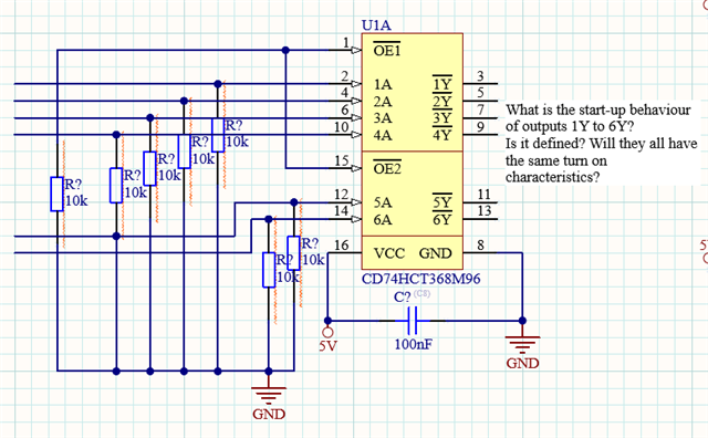
I'd like to know how the outputs start up at power on with the following configuration. It's important to us as we have relay connected at the outputs and if the outputs do not behave predictably, there's the possibility that a short circuit might be created, even if just for a short time, we try to avoid this.

I am trying to figure out whether it's good enough to constantly enable the driver via pull down or if I need some kind power on reset circuit.

We want to constantly enable, unless it's necessary to make it more complicated because of start-up undefined states.

I understand from the E2E thread below that the output of flip-flops, latches and registers are unknown on power up. However, is the output for buffers like CD74HCT368 is also unknown on power up?

e2e.ti.com/.../faq-what-is-the-default-output-of-a-latched-device-flip-flop-latch-register

Regards,

Danilo

  • Hi Danilo,

    This device is an inverting buffer - ie there is no memory to clear at startup. The output is equal to the input if the power is applied.

    During a power-up ramp the output can be erratic below the operating voltage range, but within the operating range the output will be the inverse of the input. This device has an operating voltage range of 4.5V to 5.5V, so the outputs are only specified by TI to function within that range.

    Realistically, the device will start to work around 1.5V to 2V and will continue to function normally until the operating range is reached. In other words, with the inputs held low (as shown), the outputs will follow the supply from ~1.5V to 5V.

    -

    The outputs can be put into a high-impedance state during power-on that will be consistent through the entire power ramp by holding the OE\ pin in the HIGH state (usually achieved with a pull-up resistor to VCC).