This thread has been locked.

If you have a related question, please click the "Ask a related question" button in the top right corner. The newly created question will be automatically linked to this question.

SN74AUP3G17: SN74AUP3G17(SCHMITT-TRIGGER BUFFER) Output Rise/Fall Time

Part Number: SN74AUP3G17
Other Parts Discussed in Thread: SN74AUP1G125, SN74AUP1G32

Dear Sirs:

Regarding the SN74AUP3G17(SCHMITT-TRIGGER BUFFER) Output Rise/Fall Time.

1. SN74AUP3G17(SCHMITT-TRIGGER BUFFER) VCC is 3V. 

Please provide us with theSN74AUP3G17(SCHMITT-TRIGGER BUFFER) Output Rise/Fall Time.(max) value.

2.  SN74AUP3G17(SCHMITT-TRIGGER BUFFER)

VCC = 3V ( 3.3 V ± 0.3 V ) , tpd(Max) = 7.7ns. 

The Output Rise/Fall Time.(max) value doesn't exceed the 7.7ns.

Is it correct?

Please check to reply us asap.

Best Regards

Thanks a lot.

Vincent  

  •  Dear Sir:

    Regarding the SN74AUP3G17(SCHMITT-TRIGGER BUFFER) Output Rise/Fall Waveform with overshoot/undershoot issue.

    According to the actual measurement.

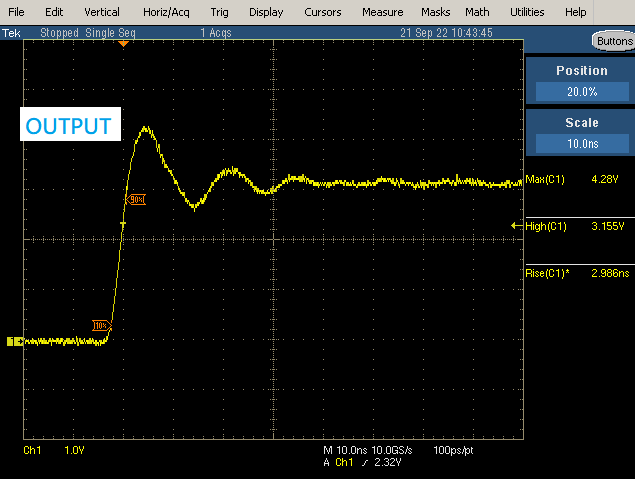
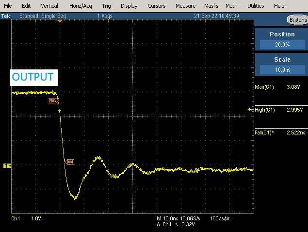
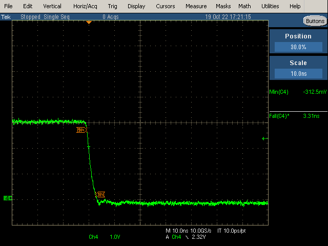
    The output of SN74AUP3G17(SCHMITT-TRIGGER BUFFER) has the overshoot/undershoot. (refer to the attached file)

    1.Which method can improve the overshoot/undershoot ?

    Whether it can improve overshoot/undershoot. to add series Damping resistor or RC Circuit( for RC dealy time to make the rise/ fall time slower) ?  

    2. Please provide us with the recommend value.

    * Recommend Damping resistor range.

    * RC Circuit : Recommend resistor and capacitor value range.

    Please check to reply us asap.

    Thanks a lot.

    Best Regards.

    Vincent

    Output Rise:

     Output Rise

    Output Fall:

    Output Fall

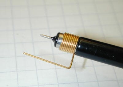
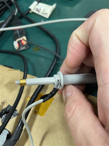
  • 1. To remove measurement artifacts, use a shorter oscilloscope ground clip, or better a ground spring as shown below:

    2. AUP outputs at 3.3 V have a typical impedance of about 55 Ω. The source termination resistor should increase the total impedance to match the characteristic impedance of the trace. That resistor is typically less than 50 Ω; try 33 Ω or 22 Ω. (AUP outputs are rather weak and should not need much impedance matching; I suspect this is mostly a measurement problem.)

  • Dear Sir:

    We use a shorter oscilloscope ground clip.

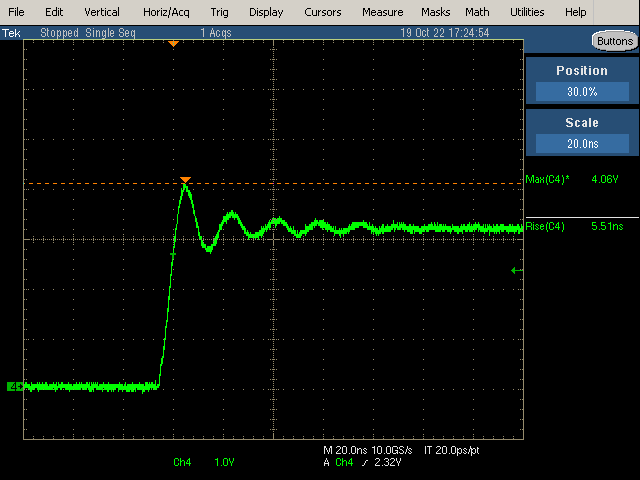
    The output waveform of SN74AUPXG17(SCHMITT-TRIGGER BUFFER is better than before.

    But the rise waveform still has overshoot. Is the rise waveform normal?

    Please provdie us with the improvement recommend.

    Thanks a lot.

    Best regards,

    Vincent

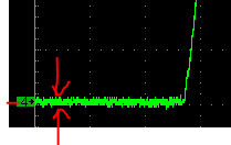
    Rise

    Rise

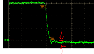
    Fall

    Fall

    use a shorter oscilloscope ground clip.

  • This is strange; rising and falling edges should be similar.

    See my first answer for recommendations.

  • I noticed that your output is driving below ground in one scope shot, but staying direct at ground in another:

    Although this is minor, it could indicate that there's some shifting of the ground in your circuit.

    That coupled with the ringing only on the rising edge leads me to believe that you may not have sufficient bypass capacitance -- your supply may have a large loop inductance, while the ground connection has a smaller loop.

    Is the device bypassed with 0.1uF placed near the positive supply pin?

  • Dear Sir:

    Is the device bypassed with 0.1uF placed near the positive supply pin?

    --> We didn't place the 0.1uF near the positive supply VCC pin. 

    We will place it and re-test.

    Thanks a lot.

    Best Reqards,

    Vincent

  • Dear Sir:

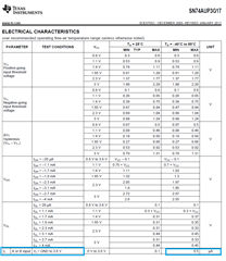
    SN74AUP3G17(SCHMITT-TRIGGER BUFFER) has the 3 channels the input.

    The current of input(Ii) is 0.5uA.

    The 3 channels input total curent : 3 channel * 0.5uA = 1.5uA. Is it correct.

    Please check to reply it asap.

    Thanks a lot.

    Best Regards.

    Vincent


  • This is correct; CMOS inputs have an extremely high impedance. (And that 0.5 µA is the worst case at the most extreme temperature; typical input current is orders of magnitude smaller.)

  • Dear Sir:

    Previous question: TI has already replied it.

    SN74AUP3G17(SCHMITT-TRIGGER BUFFER) VCC = 3V ( 3.3 V ± 0.3 V ) , tpd(Max) = 7.7ns. 

    The Output Rise/Fall Time.(max) value doesn't exceed the 7.7ns.

    TI reply: Correct.

    Currently, Just double confirm the others AUP family IC SN74AUP1G125 and SN74AUP1G32.

    1.SN74AUP1G125(Single Bus Buffer Gate With 3-State Output):

    VCC = 3V ( 3.3 V ± 0.3 V ) , tpd(Max) = 7ns. The Output Rise/Fall Time.(max) value doesn't exceed the 7ns.

    Is it correct?

    2.SN74AUP1G32(Single 2-Input Positive-OR Gate):

    VCC = 3V ( 3.3 V ± 0.3 V ) , tpd(Max) = 7.8ns. The Output Rise/Fall Time.(max) value doesn't exceed the 7.8ns.

    Is it correct?

    Please reply us the above 2 items asap.

    Thanks a lot.

    Best Regards

    Vincent  

  • Dear Sir:

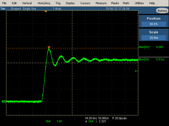
    The output of SN74AUPXG17(SCHMITT-TRIGGER BUFFER) connects to input of SN74AUP1G125(Single Bus Buffer Gate With 3-State Output)

    Absolute Maximum Ratings : The input voltage(VI) (max) of SN74AUP1G125(Single Bus Buffer Gate With 3-State Output) is 4.6V

    The output waveform of SN74AUPXG17(SCHMITT-TRIGGER BUFFER) has the overshoot.

    The output waveform max voltage level of SN74AUPXG17 is 4.06V < 4.6V.

    It doesn't cause the SN74AUP1G125(Single Bus Buffer Gate With 3-State Output) damage.

    Is it correct?

    Please check to reply us asap.

    Thanks a lot.

    Best regards

    Vincent

    The output waveform of SN74AUPXG17(SCHMITT-TRIGGER BUFFER) has the overshoot.:

  • Correct; the output rise/fall time is always shorter than the propagation delay.

    An overshoot to 4.06 V is OK. (And again, this looks like a measurement artifact.)

  • Dear Sir:

    The output rise/fall time is 10% ~ 90%. Is it correct?

    Please check to reply us asap.

    Thanks

    B.R

    Vincent

  • Yes, 10% to 90% is a common way to measure the rise/fall time.