This thread has been locked.

If you have a related question, please click the "Ask a related question" button in the top right corner. The newly created question will be automatically linked to this question.

SN74LV123A: Power-Down Considerations - protection diodes at pin 2 or pin 14

Part Number: SN74LV123A
Datasheet 10.2.1.1 Power-Down Considerations:

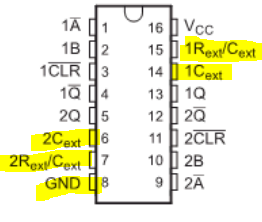
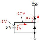
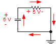
-- When a system containing this device is powered down, the capacitor can Discharge from VCC through the protection diodes at pin 2 or pin 14.
-- I think that the built-in protection diode is connected between the Rext/Cext pin and VCC, so Isn't it pin 7 or pin 15 (Rext/Cext) to VCC instead of pin 2 or pin 14?

Regards,

Kohei Sakata
  • Hello Sakata-san,

    Thank you for pointing out this inconsistency. I will mark it as a fix to be made the next time this datasheet is updated.

    This statement is in regards to the energy being discharged from the capacitor into the device, which can occur through pins 6, 7, 8, 14, and 15 with both positive and negative clamp diodes.

    These are all directly connected to the capacitor (pin 8, GND, may or may not be directly connected, depending on your system - both are acceptable). When the system voltage is suddenly reduced to 0, the capacitor will discharge through any or all of these diodes and can cause damage if the current exceeds the absolute maximum clamp diode current in the datasheet. I would recommend to keep that current below 10mA to avoid any possible issues.

    The best solution is to control the supply ramp rate such that the capacitor is discharged slowly through the diode(s). The ramp rate is related to the capacitor current via this equation:

    i = C * dv/dt

    Assuming a constant ramp rate, we can replace dv/dt with a constant value.

    For example, a 10uF capacitor being discharged at 1V per 10ms will have a constant current of i = 1V/10ms * 10uF = 1mA

    The same 10uF capacitor being discharged at a rate of 1V per 1us will have a constant current of i = 1V/1us * 10uF = 10 A

    If the supply ramp rate cannot be controlled, the next best option is to use an external diode that can handle the required current.

  • Hello Maier-san,

    Thank you for your answer.
    Please confirm additionally.

    - This statement is in regards to the energy being discharged from the capacitor into the device, which can occur through pins 6, 7, 8, 14, and 15 with both positive and negative clamp diodes.

    Does this mean that not only Rext/Cext -> VCC but also Rext/Cext (pins 7 and 15), Cext (pins 6 and 14), GND, and VCC occur as clamp diode discharge paths in the device?

    When the system power is turned off, do you mean that the discharge path of the capacitor is discharged from the + side of the capacitor, Rext/Cext, in the direction of VCC through the internal clamp diode?

    Regards,

    Kohei Sakata
  • Hello Sakata-san,

    Does this mean that not only Rext/Cext -> VCC but also Rext/Cext (pins 7 and 15), Cext (pins 6 and 14), GND, and VCC occur as clamp diode discharge paths in the device?

    If your capacitor is charged to a positive voltage, as it should be, the current will discharge through the positive diode, so the main area of concern is the Rext/Cext pin's diode that connects to the VCC pin internally.

    The important thing is that the ramp rate is limited to prevent damage to the diode if you are using a large capacitor.

  • When the system power is turned off, do you mean that the discharge path of the capacitor is discharged from the + side of the capacitor, Rext/Cext, in the direction of VCC through the internal clamp diode?

    To discharge a capacitor that is charged to a positive voltage, conventional current must flow into the negative side and out of the positive side.