Part Number: SN74LVC3GU04
Let me return to the topic, because not only did I find a useful application scenario for this special usage (which I also ran a basic test with), I also found - doubts:
A current mirror that doubles the current is a kind of amplifier and thus useful if deployed creatively.
But for a current mirror (let us assume we use the lower N-channel FETs and, as said before, Vcc is unconnected) we do not know the voltage at the drain, we only know the current there.
Depending where that output drain is connected its could be higher than the voltage on the first FET's drain (the one which is connected to the gates).
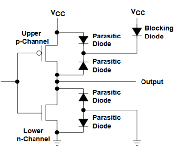
Now I was told that for LVC logic there is a parasitic body diode for the P-channel FET to Vcc although it is not specified.
This would propagate the N-channel FET's drain voltage to Vcc which is not yet a problem.
But Vcc is also connected to the first inverter's P-channel FET.
Given that the first N-channel FET's gate voltage may well be low (in a current mirror situation) this would turn on its associated P-channel FET i.e. the common Vcc node would clamp the second N-Channel FETs drain voltage to the first FET's.
Which is, of course, not what is expected from a current mirror.
The trick of leaving Vcc of a triple (or dual) unbuffered inverter unconnected (or vice versa its Gnd) is maybe not as good as it looked.
Now the question is: What's the ground truth about that parasitic clamping diode to Vcc at the (unbuffered) inverter's output?
Is there maybe a different logic family such as AUP/AUC where that diode is REALLY not there?
Actually any parasitic path may turn on the P-channel FET. Should Vcc better be connected to Gnd in such a case or would that turn off the N-channel FET too (e.g. in LXC)?
Some logic families promise that the output is high impedance if Vcc is down (AUP1T34) i.e. there cannot be a parasitic clamping diode.
The practical problem is that there is no AUP3GU04 or similar...