Dear, support team.
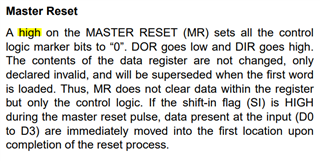
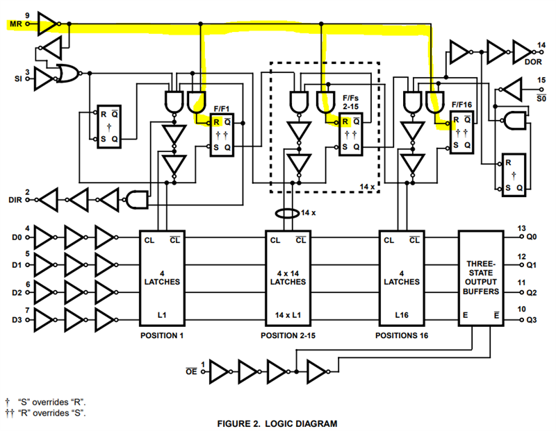
In the data sheet of "CD74HCT40105", the Master Reset signal states that it is reset by inputting a pulse signal.
Please tell me the details of the pulse signal.
・Low time from power ON to rise of MR signal
・If the power ON and MR signal rise timings are the same, will the reset be enabled only by the fall of the MR signal?
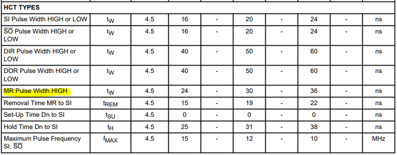
*In the specifications, the time for the High section of the reset pulse is described, but I couldn't find it for Low.
Best Regards,
Hiroaki Yuyama