This thread has been locked.

If you have a related question, please click the "Ask a related question" button in the top right corner. The newly created question will be automatically linked to this question.

SN74221: SN74221NE4 regarding the pulse width related query

Part Number: SN74221
Other Parts Discussed in Thread: CD74HCT221,

When I refer SN74221NE4 datasheet, they suggested to consider as ln2.

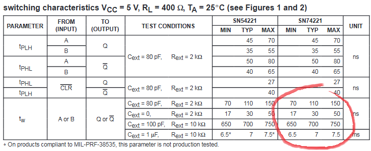
From the agile we see the part# we are using is SN74221NE4, referring to the datasheet :

  tw(out) = CextRext In2 ≈ 0.7 CextRext

R54 1% TOL                  
2100 21 2079 2121     ln2 R54 C28 TP32  
            0.693147 2.10E+03 1.00E-07 1.46E-04 Ideal
C28 10% TOL         0.693147 2.08E+03 9.00E-08 1.30E-04 Min
1.00E-07 1.00E-08 9E-08 1.1E-07     0.693147 2.12E+03 1.1E-07 1.62E-04 Max


tw(out) = CextRext In2 ≈ 0.7 CextRext

I have an observation, In our board if R value is 2.1K ohm and C value is 0.1uF, I was trying to check overall min and max pulse from the multivibrator based on component tolerances as shown in above table.

Overall from theoretical calc, I see range of 130 us to 162 us, Vs my onboard measurements are under 130us. (In the range of 125us, while the input trigger is varied from 1khz to 8khz).

Am trying to understand, if am missing something?

Appreciate your feedback/comments.

  • As shown in the switching characteristics table for tw, the tolerances are much larger than that.

    (Why are you using an old TTL device? The CD74HCT221 would use much less power.)

  • Hi,

    Thank you for quick response.

    This is a legacy design, presently we have not planned for updating the old design, unless we fall into obsolescence.

    I see the pin names are one to one between the CD74HCT221 vs SN74221NE4, I will double check if we can replace, most of the design changes expectations are to have minimum unless mandatory due to obsolescence. 

    Referring to your response on Tw, tolerances you are mentioning about, are they  figure 5 and figure 6 from the datasheet?

    figure 5 due to temp variations at the max is 0.42us, 

    figure 6, it does match with the theoritical calculations(with R value of 2.1kohm, c value as 0.1uf) i shared in my previous post, but does not match with practical measurements, unless there is any internal or onbard parasitic capacitances.  I did measure onboard with LCR meter, it was coming to around 92nf for 0.1uf onboard capacitor

  • Figures 5 and 6 show typical values.

    The switching characteristics table has guaranteed limits for some example values (but only at 25 °C, and for exact Cext/Rext values):

  • Hi,

    presently my test conditions are in room temperature range, board is just on bench top set up and not enclosed.

    If i just use the mentioned table values, am not sure what are the component tolerances considered for the given table herewith.

    I tried to calculate with those RC's, for C values i did consider both 10% and 5% as tolerance in the following table.

    They dont match for the first set of values in case of 10% or 5 % tolerance.

    But there is nearest approximation for last set of two values, if i consider 5% tolerance for the capacitor.

    R 1% TOL                   R 1% TOL                  
    2000 20 1980 2020     ln2 R C TW   2000 20 1980 2020     ln2 R C TW  
                0.693147 2.00E+03 8.00E-11 1.11E-07 Ideal             0.693147 2.00E+03 8.00E-11 1.11E-07 Ideal
    C 10% TOL         0.693147 1.98E+03 7.20E-11 9.88E-08 Min C 5% TOL         0.693147 1.98E+03 7.60E-11 1.04E-07 Min
    8.00E-11 8.00E-12 7.2E-11 8.8E-11     0.693147 2.02E+03 8.8E-11 1.23E-07 Max 8.00E-11 4.00E-12 7.6E-11 8.4E-11     0.693147 2.02E+03 8.4E-11 1.18E-07 Max
    R 1% TOL                   R 1% TOL                  
    10000 100 9900 10100     ln2 R C TW   10000 100 9900 10100     ln2 R C TW  
                0.693147 1.00E+04 1.00E-10 6.93E-07 Ideal             0.693147 1.00E+04 1.00E-10 6.93E-07 Ideal
    C 10% TOL         0.693147 9.90E+03 9.00E-11 6.18E-07 Min C 5% TOL         0.693147 9.90E+03 9.50E-11 6.52E-07 Min
    1.00E-10 1.00E-11 9E-11 1.1E-10     0.693147 1.01E+04 1.1E-10 7.70E-07 Max 1.00E-10 5.00E-12 9.5E-11 1.05E-10     0.693147 1.01E+04 1.05E-10 7.35E-07 Max
    R 1% TOL                   R 1% TOL                  
    10000 100 9900 10100     ln2 R C TW   10000 100 9900 10100     ln2 R C TW  
                0.693147 1.00E+04 1.00E-06 6.93E-03 Ideal             0.693147 1.00E+04 1.00E-06 6.93E-03 Ideal
    C 10% TOL         0.693147 9.90E+03 9.00E-07 6.18E-03 Min C 5% TOL         0.693147 9.90E+03 9.50E-07 6.52E-03 Min
    1.00E-06 1.00E-07 9E-07 1.1E-06     0.693147 1.01E+04 1.1E-06 7.70E-03 Max 1.00E-06 5.00E-08 9.5E-07 1.05E-06     0.693147 1.01E+04 1.05E-06 7.35E-03 Max
  • There are no tolerances on the R/C values. When the datasheet says that C=1µF,R=10kΩ results in 7 ms ± 0.5 ms, then that is the tolerance of the SN74221 itself. Any tolerances on the R/C values will increase the tolerance on the result.

    In practice, for your circuit's values, the SN74221 has a tolerance of roughly ±7 %. Including the R/C tolerances, the total tolerances will be about ±19 %.