This thread has been locked.

If you have a related question, please click the "Ask a related question" button in the top right corner. The newly created question will be automatically linked to this question.

SN54S140: FK package dimensions not in the datasheet

Part Number: SN54S140

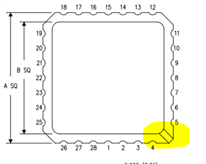
My customer is using the SN54S140.  The dimensions for the FK 20 package are not in the datasheet.  Also, the image in the datasheet shows that the pad for pin 1 is larger than the pad for other pins.  The "Generic Package View" document shows no additional information.  The Ultra Librarian "footprint" shows the pad for pin 1 as being the same size as the other pads.  The "3D Model" shows the pad for pin 1 as being larger than the other pads.  What is correct?  If the pad for pin 1 is larger, what are its dimensions?  

Thanks for your help!

  • Found a document for the generic FK (S-CQCC-N**) package with a Google search. Max height, pitch, as well as X & Y dimensions match the values at the top of page 11 of the SN54S140 datasheet. It looks like there is some portion of a pad under pin 1 but it's not called out so can't directly infer any dimensions from it or if it's connected to anything.

    https://www.ti.com/lit/ml/mlcc006d/mlcc006d.pdf

  • Hi Joey,

    It looks like the mechanical drawing of the FK package is not being correctly attached as it should -- I found the same issue in other datasheets as well. I will look into this to resolve it.

    -

    The drawing Seth linked to is correct.

    The pin 1 indicator is the different corner of the device:

    Placing that at the top left will mean that pin 1 is in the center of the top row of pins.

    The pin 1 extension on the bottom can be in several forms, but it won't impact the footprint - there is no need to add an extended pad to match on the PCB.

    I have seen this with a small disconnected circle, a connected square, and with the pin just appearing longer than others.