This thread has been locked.

If you have a related question, please click the "Ask a related question" button in the top right corner. The newly created question will be automatically linked to this question.

SN7407: Buffer Output Issue

Part Number: SN7407

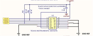
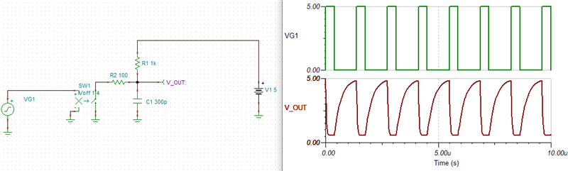
I am using the SN7407N IC to send a square wave signal through.  On a scope, I can see the signal getting to the input of the buffer but the output of the buffer is non-existent (no output).  I am using 2 of the 6 buffers on this IC.  For the unused buffers I have tied the buffer inputs to ground per the datasheet.  I am using 10K pull-ups to 5V supply for the buffer outputs.  I am trying to understand why I see no output on both of the actively used 2 buffers.  What am I doing wrong?  Please see my schematic attached.  Thanks!

  • In theory, this should work.

    What are the input voltages? What exactly do you mean with "no output"; is the output high, or low, or floating?

    (And why are you using a decades-out-ot-date TTL device?)

  • Input Voltages are from 0-5V.  No output means the line is pulled low.  We have used SN7407 in the past so kept to an IC I knew about.  

  • Hey Dan,

    I noticed that the 5V supply is labelled as VREF -- could it be that the supply cannot provide enough current to operate the device?

  • Can you double-check the input voltages? (But even an AC signal with ±2.5 V would be enough to be read as high by a TTL input.)

    If the supply and input voltages are correct, then the chip must be defective or fake.

  • The supply inputs coming in to the buffer are 5V but use non-return to zero binary data pattern with the following transmission:

    The data is transmitted using Non-return to zero binary code where:

    T0High 0 code, High Voltage Time 300ns +80ns
    T0Low 0 code, Low Voltage Time 900ns +80ns
    T1High 1 code, High Voltage Time 900ns +80ns
    T1Low 1 code, Low Voltage Time 300ns +80ns
    The frequency of the signal is 830KHz and the period is 1.2us. Can this chip handle this frequency? If not, what TI buffer would you recommend I move to instead? I am using the buffer to protect test equipment cards.

    Thanks!

  • Hey Dan,

    I'm just going to assume that you're inputting 0V for low, and 5V for high. In that case, assuming a 50pF load and the 10kohm pull-up resistor you indicated, the output would look something like this simulation:

    In my simulation, I'm using a perfect 5V input signal to trigger a 25 ohm switch to ground, similar to an open-collector device like SN7407. I copied the timings from your signal T0.

    Based on the issue you are having, I expect that your loading is larger than 50pF, so you may be getting something more like this:

    You can decrease the pull-up resistor value to help improve the rise time (rise time is 2.2 * R * C)

    If your capacitive load is large, I would recommend to also add a series resistor at the device output to prevent damage: