This thread has been locked.

If you have a related question, please click the "Ask a related question" button in the top right corner. The newly created question will be automatically linked to this question.

LSF0204-Q1: Output voltage not as expected (downtranslation, unidirectional)

Part Number: LSF0204-Q1

Hi guys,

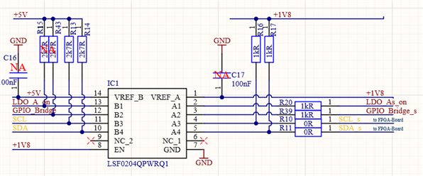
I`m using the LSF0204QPWRQ1 for a downtranslation from 5V to 1.8V side. 

Two pins are for I2C (B3, B4) and B1,B2 are GPIO-Pins coming from a uC 5V side. 

The issue is I measure at Pin A1/A2 1.97V but the VREF_A is 1.80V. 

Where does that 0.2V increase come from or what can I do? 

There is nothing else on the +1V8 rail which consumes current. I tried so solder a 2kR resistor in case there is a current flowing into the source which levels up my 1.8V rail. But there was not difference, still 1.97V. 

Any hints or advices?

Thanks,

Markus

  • Hi Markus,

    Your concern seems to be associated with your LDO supplies. Could you try different supplies to verify? 

    Note that, most linear regulators may not function properly if current is sinking into them as they are designed to provide power by sourcing current. To help ensure the VREG can sink current, please also see “understanding the bias circuit for the LSF” video from Understanding the LSF family of bidirectional, multi-voltage level translators further clarifying how current flows from Vref_B into Vref_A during normal operation. With the voltage floating up, you can also try adding a resistor from VREF_A to GND to sink the current. A 100kΩ resistor should be sufficient and can be added directly at the output of the regulator, thanks.

    Best Regards,

    Michael.

  • The LSF is a passive switch with open-drain outputs. You should add pull-up resistors at A1/A2.

    (Why are there 1 kΩ series resistors?)

  • Hi Michael,

    thanks for your answer and help! That was also one of my first ideas. For the first trials I even had a good external power supply so get the 1.8V but later one yes it will come from an LDO. So I soldered a 2kOhm resistor between Vera_A and GND but the problem was still there. :-( I made that exactly cause of the video you showed and they said that about sinking currents. But seems to be not the answer :-(

    Kind regards,

    Markus

  • Hi Clemens,

    ignore the 1kR in series :-) The devices behind are drawing low currents and I wanted to be sure in case of failures the current is limited or touching the pins cause of ESD events. 

    But coming back to the original problem of haven a too high voltage at A1/A2

    In the videos of TI they said if the device behind is consuming a current <1uA it is NOT necessary to place a pull-up! 

    Secondly - but that's now new I placed a 2.7kOhm resistor as pull-ups (behind the 1kR) and after that the level shifter seems to be destroyed. I can't believe that's cause of that pull-up but it happened. (ESD I would say not cause working in a pretty nice ESD protected environment). Destroyed meens even now without the pull-up at A1/A2 the output level is now 2.7V and not 2V anymore!? But I have a send PCB here which shows again "just" the 2V instead of the 1.8V output level...

  • Hi Mark,

    Could you help confirm if no difference with a weaker pull-down such as 100K?

    Best Regards,

    Michael.

  • Hi Michael,

    I will try that today with a weaker one from 1.8V to GND. 

    Another issue I had in mind - the 1kR pull-ups on A3/A4 couldn't have a negative influence on all the outputs? 

    What makes me really concerning is that my trial soldering a 2.7kR pull-up on A1/A2  seems to have damaged the IC. 

  • By the way for better understanding - how does it work for a down translation if B-Side is HIGH that the A-Side is also HIGH without a pull-up resistor? 

    https://www.ti.com/video/series/understanding-the-lsf-family-of-bidirectional--multi-voltage-lev.html?keyMatch=LSF

    In that video they showed that the pass transistor is open and the A-Side high voltage coming from the pull-up. But in case of <1uA of leakage it could be removed. But I don't understand what happens here then...

  • Finally the solution from Clemens solved it. I put pullups on A1/A2 (470R) and it worked. Also removed the 1kR (--> 0R). 

    Regarding to the video I posted today I thought there is no pullup needed in case of <1uA of leakage current...