This thread has been locked.

If you have a related question, please click the "Ask a related question" button in the top right corner. The newly created question will be automatically linked to this question.

LSF0108: Level translation model

Part Number: LSF0108
Other Parts Discussed in Thread: LSF0101

Hi Team,

I have a few questions about the IBIS model of this part. 

A customer was trying to simulate some signals that use the LSF0108RKSR to go between 1.8V and 3.3V and wanted to know if the model allows simulation through the actual part so they can see the level translation from input to output with whatever series impedance the part inserts?

The datasheet has many cases and examples of different resistor combinations, can you point me to a section more specific for 1.8V to 3.3V? They have two signals that go from 1.8V to 3.3V and a third from 3.3V to 1.8V.

Also, the resistors in the datasheet are for level translation and not really for signal integrity, when the switch is closed, they may need a terminator at the far end that is not necessarily the pullup R. can you suggest how to simulate this? will the IBIS model help?

Let me know if you need more information.

Regards,

Marvin

  • Hi Marvin,

    A customer was trying to simulate some signals that use the LSF0108RKSR to go between 1.8V and 3.3V and wanted to know if the model allows simulation through the actual part so they can see the level translation from input to output with whatever series impedance the part inserts?

    Please note that the IBIS models are designed to verify signal integrity for the voltage node. The device is also a passive switch; without any buffered I/Os to be modelled with IBIS i.e  operating similar to analog behaviors with the IBIS model operating just like a switch. 

    Hence, the model cannot translate 1.8V input to a 3.3V output for example, as it can only do the same voltage translation and will recommend using the simulation provided in your referenced thread. 

    The datasheet has many cases and examples of different resistor combinations, can you point me to a section more specific for 1.8V to 3.3V? They have two signals that go from 1.8V to 3.3V and a third from 3.3V to 1.8V.

    The pull-up resistor size is not solely based on the voltage but also the IOL and VOL as well, shown in equation (3) of the datasheet.

    For example 3.3V requires a 369 ohm pull-up for VOL of 0.35V with IOL of 8mA, while 1.8V requires 181 ohms.

    Also, the resistors in the datasheet are for level translation and not really for signal integrity, when the switch is closed, they may need a terminator at the far end that is not necessarily the pullup R. can you suggest how to simulate this? will the IBIS model help?

    The pull-ups determine the IOL drive strength. Hence, can improve signal integrity while driving higher loads. See up and down translation videos from  Understanding the LSF family of bidirectional, multi-voltage level translators .

    Termination would help with impedance mismatch (if any) of the signal, acting as a damping resistor. See [FAQ] What happens when I connect a logic device's output to a 50 ohm transmission line?, thanks.

    Best Regards,

    Michael.

  • Hi Michael,

    the model cannot translate 1.8V input to a 3.3V output for example, as it can only do the same voltage translation and will recommend using the simulation provided in your referenced thread. 

    Would you kindly clarify this?  By “same voltage translation” do you mean they can use the model to translate from 1.8V to 1.8V or 3.3V to 3.3V?  

    Also, I understand that the model will not do any level translation from input to output.  But, will it model just an output that I want to run at 3.3V with the functionality of the switch turning off and the external pull taking the signal higher?  

    Reards,

    Marvin

  • Hi Marvin,

    Would you kindly clarify this?  By “same voltage translation” do you mean they can use the model to translate from 1.8V to 1.8V or 3.3V to 3.3V? 

    Apologies for the confusion. No you can not translate with the IBIS model as you can mainly observe the performance of the the output's signal integrity modeling just the output similar to your understanding. It will also model the output with the switch off i.e showing signal integrity at 3.3V, thanks.

    Best Regards,

    Michael.

  • Hi Michael,

    They use the simulation file provided in the reference thread but when they look at the IBIS file, there are many models. 

    They understand that they can’t simulate actually “through” the part but just the I/O.  There are multiple models with 18 and 33 in the name.  What should they be using for 1.8V  to 3.3V translation?  Is there a document that describes what these models do?

  • Hi Marvin,

    I believe the referenced thread provided a TINA model (/cfs-file/__key/communityserver-discussions-components-files/151/LSF0108_5F00_1MHz_5F00_1V05_5F00_3V3.TSC).

    For the IBIS model, please see TI IBIS File Creation,Validation,and Distribution Processes, and you may use _IO_33 for 1.8V to 3.3V translation, thanks.

    Best Regards,

    Michael.

  • Hi Michael,

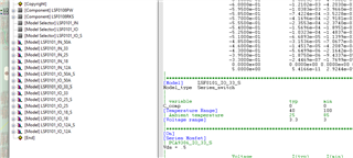
    I have a follow-up question. Would you know what the difference is between the LSF0101_IO_33 and the LSF0101_IO_33_S?  I can see that one is called Terminator and the other is called Switch but when would I use one versus the other.  I could not find that info in the IBIS file creation document. 

  • Hi Marvin,

    The termination model has ground clamps for Hi-z while the switch is just the path from input to to the output i.e when enabled.

    You may use the switch model for I/O signal integrity, thanks.

    Best Regards,

    Michael