Other Parts Discussed in Thread: SN74LVTH244A, SN74LVC1G175, SN74HCS164, SN74LVC1G374, TPL7407L, SN74HCS74
Hello all,
I'm working on a two-color (Red/Green) 9x9 LED Matrix, operating at 3V with a 3mA forward current per LED and driven via a "common cathode" method. I'm interested in a shift register capable of sourcing 3mA@3V for driving the columns. I'm considering integrating a buffer for the rows, likely the SN74LVTH244ARGYR, that can manage up to 54mA per row. The architecture is similar to the one outlined in "TIDUC25–November 2016" but accommodates a 9x9 instead of an 8x8 matrix.
Here are my questions:
-
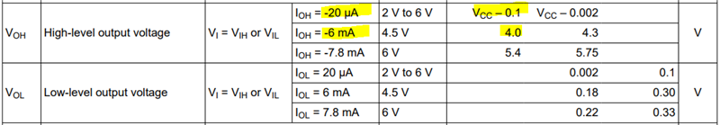
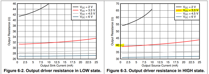
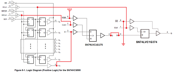
I'm considering the SN74HCS595BQBR due to its footprint, price, and availability on Digi-Key. It's suitable for my package height restriction of <1mm. However, the IC's output current appears to be insufficient. My interpolation calculation from the datasheet (20uA@2V to 6mA@4.5V) gives roughly 2.41mA @3V, which falls short. Can you verify this estimation?
-
Assuming the first point is valid, could you recommend an IC with similar specifications and a comparable footprint/price range? The SN74LV595ARGYR seems ideal, but its availability and cost are issues.
-
The main issue with this setup is that I have a 9x9 matrix, not an 8x8. Adding an extra shift register feels inefficient, so my alternate solution is to utilize FETs to drive the remaining LEDs. Are there any standard solutions to this issue?