This thread has been locked.
If you have a related question, please click the "Ask a related question" button in the top right corner. The newly created question will be automatically linked to this question.
Hi,
Can you explain what this table means from the datasheet?
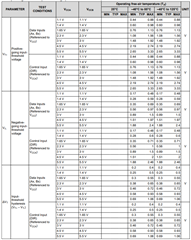
My understanding is that for the DIR pin, VT+ gives the voltage range of a logic high (A to B) and VT- gives the voltage range of a logic low (B to A). But what does this table mean for the data pins? Do these pins have logic high and logic low levels as well?
Best,
Lucas
All digital input pins have two states, high or low.
This table describes the switching thresholds; it does not care about the meaning of the pins. For the data pins, their state determines whether the corresponding output pin drives high or low.
Hi Clemens,
Does this mean this device doesn't translate the exact voltage level on pin A with respect to VCCA? For example, if VCCA = 3V, A = 1.5V, and VCCB = 5V, does this mean the voltage on pin B will be 5V or 2.5V? If A = 1V, will pin B be 0V or 1.6V?
What if the voltage on pin A is outside of the ranges specified for logic high and logic low? Is this undefined behavior?
Best,
Lucas