


Other Parts Discussed in Thread: DRV8811
Hello,
I am using a 74LVC14A inverting buffer for Vishay opto sensors, to convert 5V signal to 3.3V and feed into LPC2132 pins. The output of optosensors is fine, a good square wave but the output of schmitt trigger is distorted. Please see the scope output:
The yellow trace is optosensor output - that is input to the schmitt trigger and blue trace is output of the schmitt trigger, which is clearly going negative. There is no physical capacitor bypass between the schmitt trigger output and LPC2132 input. Could this happen because of parasitics, or bad chip? This could not be failure of a single gate since the same thing happens to other opto sensors as well.
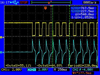
And not only this, I also use a 74HCT08 (not schmitt trigger) to convert LPC2132 output to 5V signals for DRV8811 and something similar happens:

Yellow is input to 74HCT08 and blue is its output. As the motor accelerates (the clock pulses become denser) the negative offset increases and levels off when it reaches cruise speed. The input to DRV8811 is actually +2.5 to -2.4V which is still 5V in magnitude, but only +2.5V for practical purposes. This somehow works (the motor moves) even though it is below the threshold of the DRV8811 (0.7x 5V), but I am more concerned about the negative part, which could damage the DRV8811.
Both these issues, could they be because of board quality (4-layers, made by golden phoenix prototyping service) or just bad PCB design? I am very new to analog design and not very well versed with these effects of tiny parasitic components on digital signals. So far its a dead end for me. Maybe I can try making the same PCB from another vendor, but need to know the core issue behind this fiasco.
Thanks,
Gary