This thread has been locked.

If you have a related question, please click the "Ask a related question" button in the top right corner. The newly created question will be automatically linked to this question.

TXB0104-Q1: TXB0104-Q1 circuit problem and current backflow problem

Part Number: TXB0104-Q1
Other Parts Discussed in Thread: TXU0304-Q1

Hi,

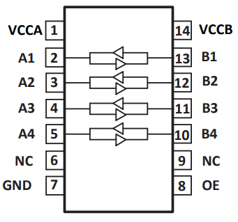
When using TXB0104QPWRQ1, we found that after the VCCB power supply is turned off, the MCU pin at B1 pulls up the 3.3v level, and the voltage at VCCB can be measured to 3.1v, and the level conversion chip can work normally. Our customer would like to ask what is the circuit between B1 and VCCB, and why there is current backdown?

  • Hey Shelly,

    This device has the VCC Isolation feature- if any one of the two power supplies are powered off and at GND, the outputs (B1 in this case) will be put into high impedance and there should be no leakage current from VCCB and B1. 

    How is the test performed? What is the voltage at A1 and could the same results be observed if the OE pin is tied low? Are you able to provide schematics/ waveforms of normal operation as well? 

    Regards,
    Jack 

  • As long as one pin outputs a high signal, there is a direct connection between the pin and VCC. So if B1 is an input, the MCU supplies current into VCCB.

    If the signals are not actually bidirectional, use a unidirectional translator like the TXU0304-Q1. Alternatively, pull OE down.

  • Hi Jack

    The specific phenomenon described by our customer is:

    The vehicle's behavior is a small probability of not waking up the MCU through the module. That is, A3 pulls up, B3 doesn't pull up. The power supply of VCCB is controlled by MCU. Due to the design defect on customer's side, VCCB cannot be maintained when MCU is asleep, and previous normal boards are all operated by 3.3v leakage of B1 to the VCCB holding level conversion chip.

    The VCCB voltage is 0v, B1 is 3.3v when the problem occurs. Both VCCA and OE pin are 1.8v.

    Our customer wants to know whether the direct connection between B1 and VCCB can stably maintain the normal operation of the chip, and under what circumstances will B1 is 3.3v and VCCB no longer have voltage?

    Thank you!

  • Hi Clemens,

    The specific phenomenon described by our customer is:

    The vehicle's behavior is a small probability of not waking up the MCU through the module. That is, A3 pulls up, B3 doesn't pull up. The power supply of VCCB is controlled by MCU. Due to the design defect on customer's side, VCCB cannot be maintained when MCU is asleep, and previous normal boards are all operated by 3.3v leakage of B1 to the VCCB holding level conversion chip.

    The VCCB voltage is 0v, B1 is 3.3v when the problem occurs. Both VCCA and OE pin are 1.8v.

    Our customer wants to know whether the direct connection between B1 and VCCB can stably maintain the normal operation of the chip, and under what circumstances will B1 is 3.3v and VCCB no longer have voltage?

    Thank you!

  • There is no guarantee that the device gets enough power through an I/O pin. (In the DC state, the outputs go through a 4 kΩ resistor.)

    This is not something that TI has characterized. You own observations/experiments show how stable it is.