


Hi
I've got PCF8523 RTC that is powered directly from a LIPO battery with a voltage range of 3-4.28V. this must communicate with the microcontroller over I2C that is running at 3V IO.
The RTC VIH is 0.7xVDD = 2.996V so conceivably i could just use the 3V supply for pullups to the RTC and it should work but it feels quite marginal having the pullups so close to the VIH limit hence (though maybe not?) I'd like to use a level translator to go from 3v to 3-4.28v.
I found this post : https://e2e.ti.com/support/logic-group/logic/f/logic-forum/576669/i2c-level-shifter-with-vary-supply-voltage-range-for-a-battery-application which uses the single supply app from the datasheet of the LSF0102 pg 17 (https://www.ti.com/lit/ds/symlink/lsf0102.pdf?ts=1690269956404&ref_url=https%253A%252F%252Fwww.google.com%252F) but this breaks the condition that "The single supply used must be at least 0.8 V larger than the lowest desired translation voltage."
When i plug in the values to the eqn on the datasheet i don't get 276.9k found in the post.
my questions are:
1) How was the resistor values for the single supply calculated in the linked post
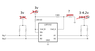
2) Can you suggest a working configuration for my circuit requirements in the img below.
3) What pullup values are appropriate for both sides of the circuit if i'm using i2c fast mode. Trying to keep power consumption as low as possible for a battery powered device.
Thanks for the help!

