A related question is a question created from another question. When the related question is created, it will be automatically linked to the original question.
If you have a related question, please click the "Ask a related question" button in the top right corner. The newly created question will be automatically linked to this question.
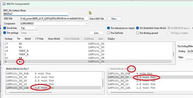
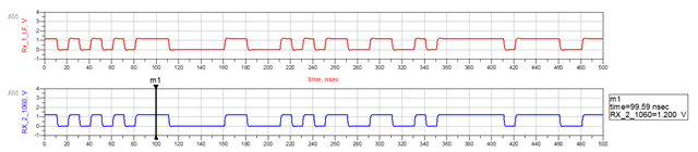
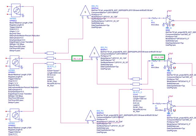
LSF0108: IBIS model issue that cannot transfer 1.2V to 3.3V
This case looks similar to this E2E thread. Could you try simulating with the input source outputting 3.3V and selecting the same voltage node (3.3V) for both Pin 3 and Pin 18?
Yes, you are correct- if they expect to see the behavior of a 3.3V output, a 3.3V model needs to be used for both input and output. However, since this translator performs level shifting passively (unbuffered outputs), it is strongly suggested to not rely on the simulations for testing signal integrity as the results can be unreliable. Usually only buffered I/Os can be accurately modelled with IBIS. I would recommend prototyping the device with the EVMs instead.
I am afraid I do not have experience with SigXplore, so I cannot provide much information on this.