Other Parts Discussed in Thread: TXU0101, 2N7001T
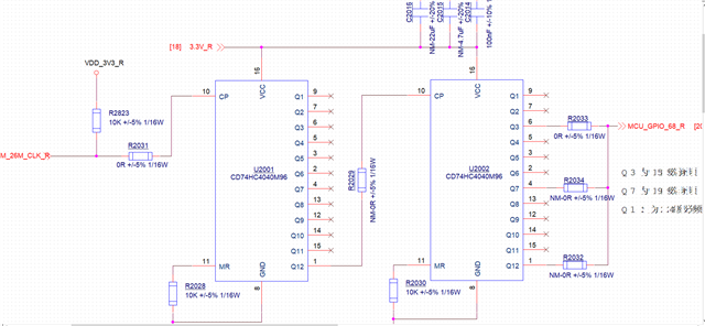
At present, the project needs to test the 26MHz CLK signal. There are the following issues with manual environment testing. Please help analyze and confirm. Thank you!
1. Can't measure the bias voltage directly by pulling up the CP pin at 3.3V, or is it the 1.8V peak voltage output by the module signal
2. Because the power supply standard voltage is only 3.3V and 5V, but our module's 26MHz frequency is 1.8V, and the frequency divider chip cannot output it
3. Attempted to reduce the power supply of the chip VCC and found that there was only output from 2.5V to 3.0V
4. Another phenomenon is that (when VCC is powered from 2.5V to 3.0V) the frequency divider chip has several grades from Q1 to Q12,
When there is no pull-up at 26MHz, there are several levels without output, and several levels with output; Then pull up to 26MHZ,
This phenomenon will be reversed. Should all grades from Q1 to Q12 be able to be output, regardless of whether they are pulled up or not