Part Number: SN74HCS74
Other Parts Discussed in Thread: SN74HCS04
Hello-
I believe that there is a further issue with the SN74HCS74 Spice model (I raised an issue in a previous thread in the E2E Forum on this topic from over 2 years ago and you resolved it).
It seems that there is excessive capacitance on all the inputs. See this schematic:
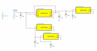
Basically, I put a "50 kHz" square wave into the clock input of the SN74HCS74. The Q_N output is connected back to the D input making a divide by 2 circuit. I also use the SN74HCS04 inverter model for comparisons. The same square wave goes into two cascaded SN74HCS04's. And finally the Q output is also sent to another 74HCS04. This is the oscilloscope view of all these signals:
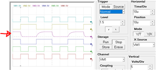
The traces are arranged with VM1 at the top and VM6 at the bottom. VM1 is the input clock. VM2 is the divided by 2 Q output. VM3 is the divided by 2 Q_N output (that is fed back to the D input). VM4 is the Q signal inverted by a SN74CHS04. VM5 is the input clock signal inverted by a SN74HCS04. VM6 is the double inverted clock from another SN74HCS04.
What this shows is that the SN74HCS74 Q_N output cannot drive its D input. As you can see on trace VM3, it has a rise time on the order of 6 or 7 uSec. and a fall time on the order of 2 or 3 uSec. But the problem is not in the SN74HCS74 output model, rather it is on the input. The Q output has no problem driving the SN74HCS04 input on VM4. And SN74HCS04 outputs can drive other SN74HCS04 inputs (VM5 and VM6). The problem is with the SN74HCS74 inputs. I have verified that this same issue exists with the SN74HCS74 clock input. If I drive the clock input with the output of a SN74HCS04 I see similar long rise and fall times. I have not checked the PRE and CLR inputs.
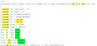
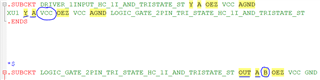
A bit of experimentation shows that the SN74HCS74 model inputs look approximately like 10 nF capacitors to ground. But the inputs used for the SN74HCS04 model seem to be fine.
Thanks!
-Randy