1. I would like to ask you how to wake-up in sleep mode when using TCAN2450-Q1.
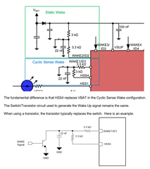
Please explain how to do cyclic sense wake design other than wake-up using mechanical switch.
ex) some sort of relay, FET, other mechanism
2. When configuring cyclic sense wake for HSS4 and WAKE1, it is said that you need to connect to the wake signal source so that you can detect the wake, so please explain how to connect in the attached Logic.