This thread has been locked.

If you have a related question, please click the "Ask a related question" button in the top right corner. The newly created question will be automatically linked to this question.

TXS0102: Short on VCCA?

Part Number: TXS0102

Hi, I have a system that has 4x TXS0102 parts for 8 I/O signals

VCCA = 1.8v
VCCB = 5v
(Both shared between all parts)

OE = tied to VCCA

There are 3 different conditions being used:
Input: A is Hi-Z FPGA input, and B is driven by other CPU
Output: A is driven by FPGA output, B is Hi-Z connected to other CPU input
Unused: A is Hi-Z, B is floating

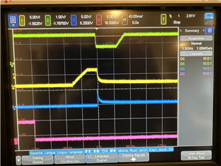
The problem is that I am seeing a condition where VCCA is pulled low for a short period to ~1.0v. Is it possible for the LXS0102 to exhibit a condition which would cause a brown-out in VCCA? Perhaps some kind of noise or transient on the input or unused pins?

  • Hello,

    The TXS0102 has internal 10kohms pullups on the I/Os so the unused pins will always be tied high and not be floating. Are there any schematics/ scopeshots that can be provided for further debugging? Is the 1V8 power supply able to stay at 1V8 if the TXS devices are no longer connected? 

    Regards,

    Jack 

  • Thanks for your quick reply Jack.

    Green = VCCA
    Yellow = VCCB
    Blue = B
    (Pink isn't related to the TXS0102)

    I don't have a probe on A, but in this case it is being driven low by the FPGA. We've also tried cases where A is either Hi-Z or driven high, but the same dropout of VCCA occurs.

    The dropout occurs shortly after the "B-side" is connected via a connector. (as detected by the pink). This connects the VCCB and the B signals to the other device.

    When VCCA (green) drops out, our FPGA resets, therefore the enable pin for the VCCB supply turns off, and the A pin goes Hi-Z, which explains the behavior in VCCB (yellow) and B (blue) afterwards.

  • Hello,

    Several questions here: 

    1. Is the anomaly gone if we do not connect the connector on B side? 

    2. How are all the TXS devices configured? Are they used in series? Daisy chain? Please provide schematic/ block diagram if possible.

    It also seems that the time scale is rather large and makes me think the input transition rate can potentially be in violation.

    Looking at the OE pin for example, it uses CMOS logic. If the input transition time is too slow, it can cause large amounts of shoot-through current as the voltage is in between the logic threshold regions. If this current is higher then the listed in abs max, it can cause permanent damage to the device. 

    Regards,

    Jack