A related question is a question created from another question. When the related question is created, it will be automatically linked to the original question.
If you have a related question, please click the "Ask a related question" button in the top right corner. The newly created question will be automatically linked to this question.
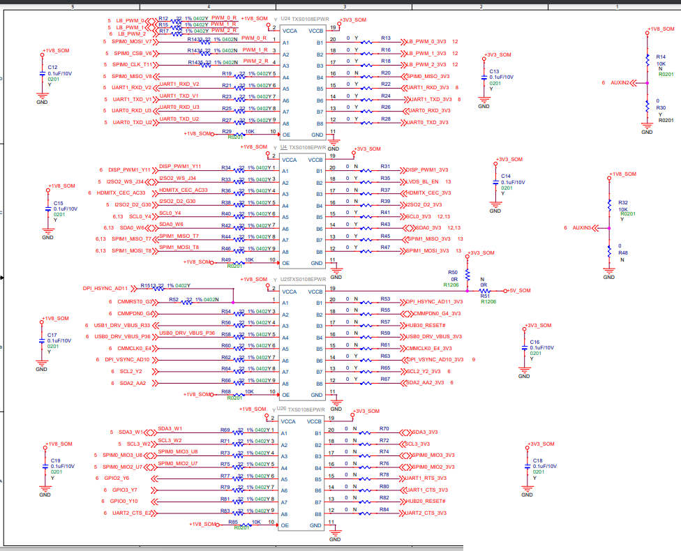
It seems that the device is being used for a variety of push-pull and open drain signals, which the TXS0108E will be able to support. The configurations in the schematic seem fine to me- bypass caps. sized accordingly, no external pullups/ pulldowns on the I/O lines since the device has internal 10kohms and VCCA <= VCCB. However, on U25, please note that when the VCCB is biased to 3V3 or 5V, the I/Os connected on B-side will see the same voltage due to the internal pullup.
There aren't any immediate drawbacks that I can think of with using the 33ohm series resistors- more so the application that I am concerned with. With the series dampening resistors in the schematic, I am assuming that the signals are being driven over long distances in effort to impedance match with a potential transmission line. Could you please confirm the length of connectors/ PCB traces is below the <70pF loading condition as mentioned in section 10.4.1 of the datasheet?