


Other Parts Discussed in Thread: SN74LVC1GX04, SN74HCU04
In the past we have ordered SN74HC02PWRE4, and designed a clock circuit with it. Recently it appears we have been ordering SN74HC02PWR and it may be causing issue with our circuit. We are guessing it's a impedance mismatch. We are attempting to create a circuit that produces a 4Mhz signal, with the recent part SN74HC02PWR it has failed to do so only producing about 68Khz. I have looked at both spec sheets and could not find a difference in characteristics.
I was wondering if there is a difference between these two parts.
Below is a section of circuitry that we are trying to make.
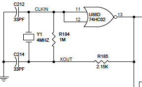
U88 is the component in question. It is receiving a 5V VCC the circuit powers a clock signal to 6 other devices, they are not causing this error.
below are some captures
This is the expected waveform at Pin 11/12 using SN74HC02PWRE4
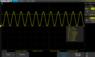
- Frequency is 4 MHz
- Pk-Pk is about 4.8V
This is the waveform at Pin 11/12 using SN74HC02PWR
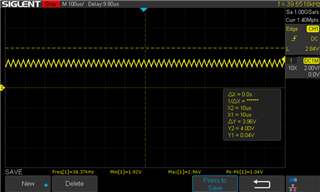
- Frequency is 38.37 kHz.
- Pk-Pk is about 1.04V
Below is the output Pin 13 using SN74HC02PWRE4
- Frequency is 4 MHz
- Pk-Pk is about 8.4V
- Rise time is 3.8ns
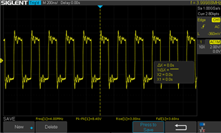
Below is the output pin 13 using SN74HC02PWR
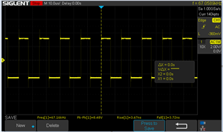
- Frequency is 67.16 kHz.
- Pk-Pk is about 8.48V
- Rise time is 3.67ns
When changing the resistor R184 from 1M to 100k ohms, this fixes the issues, but I cannot proceed with the changes unit I determine what may have caused this. Changing a resistor might suggest in changes in impedance within the SN74HC02PWR .
Hope to hear from you soon.


