This thread has been locked.

If you have a related question, please click the "Ask a related question" button in the top right corner. The newly created question will be automatically linked to this question.

LSF0108: current consumption

Part Number: LSF0108
Other Parts Discussed in Thread: TXU0204, TXB0108

hey i am a junior pcb design engineer and i have a project where i use the lsf0108 for a bidirectional voltage translation.

i need to know how much current i drive from the vcc in order to choose my power supply.

unfortunately i cant find a decisive answer in the data sheet.

i would also like to simulate the circuit, i downloaded TINA but i cant find this component there.

would love to get some help.

thanks 

  • Hi Aviv,

    Welcome to the E2E forums! I am unclear what you are asking about, did you mean how you would size the external pullups at the I/Os to limit leakage current? Is this regarding the VREFA/VREFB or the I/O channels? 

    You may also want to see The LSF Logic Minute Video Series for how the device operates and key careabouts when designing with the device. 

    I have also attached the LSF TINA model below that can be used to simulate the device (though I would still recommend the LSF-EVM to see how it performs at your system level). 

    LSF0108_Example.TSC

    Regards,

    Jack 

  • Hi Jack, thanks for the response.

    so my pcb is getting 12V and i need to convert it to3v3 and 5v 3.3 for an fpga.

    the signals that going into the fpga are differential LVDS and some of them are coming out as LVTTL. for those signals i need a bidirectional translation from 3.3 to 5 and the opposite.

    in order to chose my converters i need to know what is the current I need to supply for this component. i care about the current that is coming from the power supply and not from the signal.

    another thing, i saw that after the translation i need to have an open drain in the side where I receive the signals after the translation.

    is that mandatory? because i do only this PCB and im not in charge of the other parts in the system..

    I hope this was clearer

  • A small current flows into Vref_B and out of Vref_A; it is limited by the 200 kΩ resistor, so it is usually neligible. In practice, what matters is only the current through the pull-up resistors on the I/O lines.

    The LSF accepts both open-drain and push/pull signals on its inputs; its outputs always are open drain. (You need pull-ups on all open-drain signals.)

    If all individual signals are unidirectional, you should use unidirectional translators like the TXU0204.

  • but the current through the pu resistors is also coming from the power supply, not just the current through Vref_A and Vref_B.

    the signals i am talking about are bidirectional. this is a block scheme of the project.

    i dont know what exist after the connectors that the bidirectional signals are coming and going there...

  • Hey Aviv,

    This device does not consume much power on its own due to its FET based architecture:

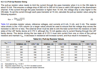
    The current being sunk through your power supplies at the I/Os will be determined by the pullups used, which need to be sized according to the data rate required by your system and the amount of leakage current back into the driver side during translation: 

    Could you provide a schematic of the signals at the I/Os of the LSF0108? Are the signals bidirectional per channel or in different channels? 

    Regards,

    Jack 

  • hey

    the signals going to the LSF0108 are all bidirectional. I still don't have an electrical scheme because I'm not sure I can use this component that is why I wanted to consult with you guys... so a 12v to 5v with 1 amps should be fine over here right? i have 5-6 of those components(lsf0108)

    the only thing im worry about is the demand for a open drain. again i am not sure what i have in one side of the translator because the signal going and coming from a connector that connects to another board.

  • Hey Aviv,

    The LSF0108 won't be able to handle the 1A coming into the device. As stated in section 6.1 of the datasheet, the max continuous current through the device is 128mA- anything greater is guaranteed to break the device (please operate under the recommended operating conditions of 64mA instead). 

    Depending on the interface of your bidirectional signals, the TXB0108 can also be realized if open drain configuration is not of need. You may also see Voltage Translation Quick Reference for more info. 

    Regards,

    Jack 

  • hey Jack,

    I feel like I confused you, I am sorry. let me try and organize it all.

    I have two issues. one is the power and the second is the bidirectional signals.

    For the power, I meant that the maximum current this device can drive is 1A.

    and the second issue:

    I have the FPGA and some of it's signals are bidirectional. when the signal comes out of the FPGA to the connector it comes out as LVTTL 3.3V and I need to translate it to TTL 5V on the connector it connects to.

    when the signal comes from the connector to the FPGA it comes as TTL and I need to translate it to LVTTL.

  • Hey Aviv,

    I cannot speak much on the power side due to my limited knowledge on that topic (sizing/ choosing which converter to use), but the power supply used will produce a small current going into VREB and VREFA that is limited to the 200kohm pullup, similar to what Clemens' has stated above. It is fairly small and will result in uA of leakage current. 

    TTL/ LVTTL signals are compatible with the LSF0108, so it can be used. You may see this E2E thread for similar use case without pullup on 5V-TTL side since the LSF clamps the output voltage on TTL side to 3.3V when LVTTL side is driving high. 

    Regards,

    Jack