This thread has been locked.

If you have a related question, please click the "Ask a related question" button in the top right corner. The newly created question will be automatically linked to this question.

TXB0102: Looking for suggestions and guidance of serial ring and level shifting design?

Part Number: TXB0102
Other Parts Discussed in Thread: SN74AHCT1G14, TCAN330, SN74LVC1G07, SN74LVC1G17

Hello, 

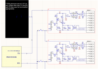
An actuator vendor provided schematics to interface circuitry between an MCU (on our end) and the actuator serial interface on (their end). The schematic sheets suggest level shifting is required for any voltage other than 5V. Looking for help and/or suggestions with the following:

1. I have been trying to convince myself that the provided circuity could very likely be reduced with lower count parts taking advantage of smaller level shifting and/or isolation ICs etc... rather than keep the vendor reference design AND add level shifting to the front end of their existing design as noted in the schematic. Snippet below. 

2. If the assumption in 1 above is incorrect would it suffice to use a TXB102 part or similar? 

Goals:

  1. Build these circuits into a custom PCB that will serially chain 8 motors so smaller component count would be desired. Each motor will require one instance of the circuit and chained as shown in the snippet.  
  2. From the schematic notes 115.2 ,230.4, and 460.8 kbps are options. It would be great to continue to support the highest data rate. I realize the TXB102 does not meet this requirement hence I just used this PN as a baseline for the level shifting series.  

Some Design Context: 

  1. Our source 3.3V UART from out MCU. 
  2. The actuators are generally designed/used in industrial environments - very noisy and very long cable lengths 10s and 50s of ft - 
  3. Our application environment is an adoption to robotics - yes probably noisy but with very short cable runs like 4ft or less.  

Looking forward to the discussion and ideas and thanks in advance for the help. 

Cheers, 


Wess

  • Is there a datasheet for this actuator? It would be helpful to know what its electrical characteristics are.

    The TX signals uses two inverter outputs in parallel. At 5 V, HC has a rated drive strength of 4 mA, so I assume the input needs 8 mA. A single level shifting inverter (e.g., SN74AHCT1G14) would be able to handle this.

    The RX signals are unclear. As far as I can see, when pin 5 is pulled high (to 5 V, or above?), the output should go low. Assuming that R11/R16 are wanted to get a certain load current, this could be handled with a comparator (I don't know what input voltage range is required), or, if you want a more robust device, a differential receiver like the TCAN330.

  • Hi Clemens, 

    Yes there is a datasheet. I did not see a way to attach a file and I think access would require signing up for a login. Did not want to trouble someone that much. Here is the link Clearpath User Manual IP67

    The actuator interface section starts on page 45 of the users manual. The input lines accept 5-24 VDC it would be nice to maintain some of the robustness I just do not have a very good feel for what "robust" means so far. 

    Thank you for the help, 

    Wess

  • When driving the negative input, you do not need an inverter. An open-drain buffer like the SN74LVC1G07 has an overvoltage-tolerant output and can be simply run with the 3.3 V supply. (The supply at Input+ still must be 5 V.)

    The HLFB+ output can be connected directly to a buffer, with just a pull-up resistor to 5 V. All LVC buffers (e.g., SN74LVC1G17) have overvoltage-tolerant inputs, so they can run with the 3.3 V supply.

    To increase robustness, you would need additional protection components. (You need to know or estimate how your environment affects the signals. To filter out high-frequency noise, add low-pass filters. To protect against overvoltage, add clamping diodes.)

  • Thank you Clemens. I really appreciate the recommendations and homework assignments Slight smile

  • Hi Wess Gates, I’m an engineer with Teknic and came across your questions about the Software Control (SC) ClearPath serial loop. Since the I/O on ClearPath is all optically isolated, the SC serial link is a current loop that travels to and from each node. The SC4-Hub circuitry was carefully designed and extensively tested to ensure this current loop is extremely noise-immune and robust at high communication speeds.

    Although it is technically possible to drive the ClearPath I/O directly (other series of ClearPath work like this), with ClearPath-SC we always recommend using the designed signal conditioning of the SC4-Hub to ensure communication reliability. For prototyping or lower volume machine builds (less than 100 machines per year, for example), we typically recommend using the Teknic SC4-Hub to reduce development and testing time. For high-volume OEMs who choose to design their own communication hub, they should copy the communication portions of the circuit for each node exactly as shown in the ClearPath-SC manual. Added level-shifting may be necessary depending on the serial port.

    For additional questions, please contact Teknic support at https://teknic.com/contact/.

    -Aaron B. Teknic Servo Systems Engineer