This thread has been locked.

If you have a related question, please click the "Ask a related question" button in the top right corner. The newly created question will be automatically linked to this question.

CD74HC4046A: Narrowband Demodulation Resistor Setting

Part Number: CD74HC4046A

Hi, I have been trying to demodulate an FSK signal at 9600 baud, and 4.8kHz frequency deviation. I don't mind what the carrier frequency of the signal is, although the higher it is the better. I have followed the application note, however the example there spans over MHz which is far to wide for me,

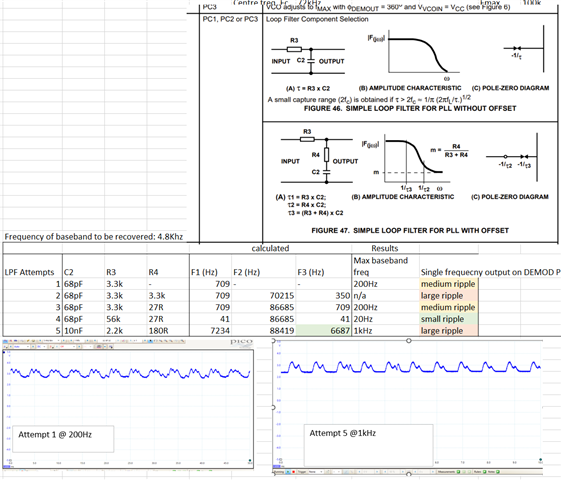
I am having trouble finding suitable R1, R2 and C1 values to meet both of my requirements - for example, using R1, R2, C1  at 3.3k, 5.6k, 100nF then the center frequency and frequency span  is reduced, to 75kHz center frequency, with a noticeable output at 4.8kHz deviation. However, then the baseband signal can only reach about 1kHz as the LPF needs to be adjusted, and if I make the cut-off any lower, then I get spikes/ instability in my output signal.

Then, with R1, R2, C1  at 100k, 13k, 200pF, the center frequency is higher - 10Mhz, a 9600Hz baseband signal can be recovered but the span is also much greater so it needs about 500kHz frequency deviation in input signal to show a change on the output. 

I have also tried a few in between this, but have not yet found a solution which allows for both 9600 baud rate and 4.8KHz deviation.  Does anyone have any advice about how to solve this problem? 

  • Hi Met, 

    Apologies for the delay, our team is currently reviewing this and we should be able to get back to you by the end of the week. 

    Regards, 

    Connor 

  • Hi Met, 

    I would recommend referencing this old E2E thread if you haven't seen it already, it goes through some more details about how to implement a modulator/demodulator pair using CD74HC4046A: https://e2e.ti.com/support/logic-group/logic/f/logic-forum/986083/cd74hct4046a-fsk-modulator---demodulator-pair-using-cd74hct4046a-unexpected-demodulator-functionality?tisearch=e2e-sitesearch&keymatch=CD74HC4046A%252520demodulation# 

    Also, you mentioned that using a 75 kHz center frequency doesn't work because the LPF isn't properly set, could you share which components you are using for the LPF and which phase comparator you are using?

    Regards, 

    Connor 

  • Hi, thanks for sharing the link. I have been through the spreadsheet and have tried calculating different values for T1, T2 and T3. Using PC2, I have tried different variations of the LPF, sometimes with just R3 and C3 resistor, sometimes with R3, R4 C2. The problem is that it gets very unstable as I increase the LPF cut-off. The ripple was mostly eliminated in attempt 4, however all the others have fairly large ripple  (for example shown in the bottom pics when trying to recover a square wave). Even with just no change to the 75kHz input to SIG IN pin, this ripple still occurs, I can attach an extra pictures if required. I have briefly tried with PC1 and PC3 but don't find much improvement. If anyone has any ideas how to eliminate this instability/ ripple, then it should be easier to adjust LPF further so that it can allow a 4.8kHz baseband to be recovered. 

  • Hi Met, 

    Would it be possible to attach a schematic of the CD74HC4046 or a block diagram of your test setup just to help me understand where the ripple is coming from?

    It looks like in the "Implementation of FSK Modulation and Demodulation using CD74HC4046A" application note there were also some issues with ripples and other noise coming through at higher modulation frequencies so they recommend sending the DEMout signal through a Schmitt trigger to sharpen the output into a proper square wave. 

    Regards, 

    Connor